Send I2C/SPI/DIO Between Devices up to 150ft Away
Designed by JARViE in United States of America
Buy with confidence.
Our Tindie Guarantee protects your purchase from fraud. Learn More
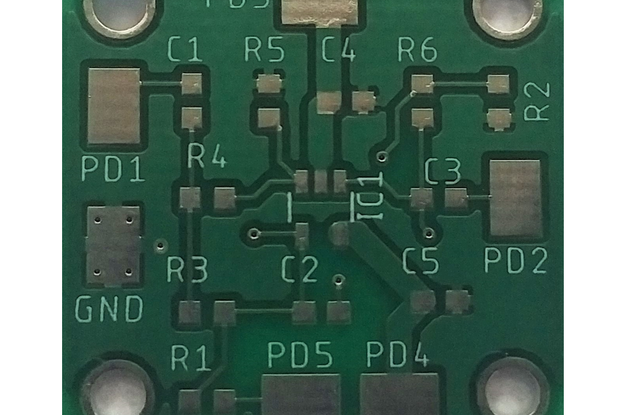
Product Description The Extender is JARViE's solution to sending up to 1 MHz data rates over cables up to 150 ft long. It uses the Texas Instrument's P82B715 buffer to send I2C, SPI and or digital I/…
Read More…The Extender is JARViE's solution to sending up to 1 MHz data rates over cables up to 150 ft long. It uses the Texas Instrument's P82B715 buffer to send I2C, SPI and or digital I/O communications over long cables.
Sending signals over long cables is a challenge! One has to account for the cable transmission properties and how it relates to electrical properties of the device sending the signals down the cable (Device A) and the device receiving it on the other end (Device B). The capacitive, inductive and resistive properties of the cable between the devices has an affect on the signal sent from Device A to B. The cable capacitance will affect max bus speed because bus capacitance is inversely proportional to the max data transmission rate. The cable resistance will cause the signal to attenuate or decrease in amplitude. The cable inductance will choke/reduce the max current the cable can carry as the frequency of the signal increases.
I2C and SPI were designed to be used in-PCB, so the total bus length shouldn't exceed about 50cm using standard bus speeds. Though reducing the bus speed can enable successful bus communications over longer cables, it is recommended to keep bus lengths at 1-2m maximum for I2C and SPI.
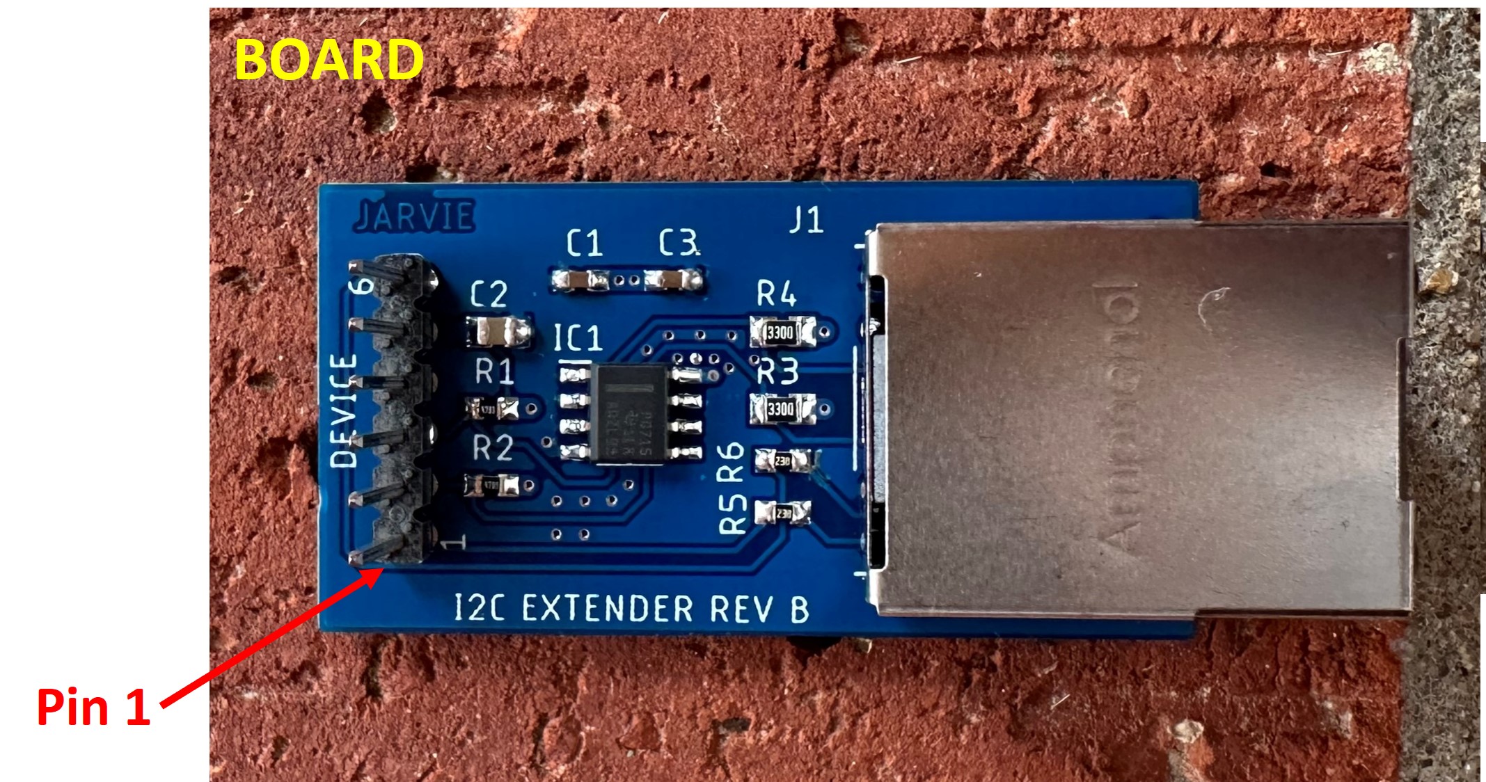
| Pin # | Signal Name | I/O | Description |
|---|---|---|---|
| 1 | GREEN LED | I | Green LED on RJ45 connector for indication. Only drive LED from DEVICE HDR pins. |
| 2 | HOST CLK | I/O | Unbuffered data bus. Connect to I2C/SPI/DIO. Signal has a 4.7k pull-up. HOST CLK and SDA circuitry are the same so pins are interchangeable. |
| 3 | HOST SDA | I/O | Unbuffered data bus. Connect to I2C/SPI/DIO. Signal has a 4.7k pull-up. HOST CLK and SDA circuitry are the same so pins are interchangeable. |
| 4 | GND | — | Ground |
| 5 | VCC | — | Buffer power supply input, sets I2C bus voltage level, rated for 3V min 12V max. If constructing a buffered cable, connect a power supply to VCC on one side of the cable only! |
| 6 | YELLOW LED | I | Yellow LED on RJ45 connector for indication. Only drive LED from DEVICE HDR pins. |
| Pin # | Signal Name | I/O | Description |
|---|---|---|---|
| 1 | VCC | — | Buffer power supply input, sets I2C bus voltage level, rated for 3V min 12V max, Buffer supply current = 22 mA @ VCC = 12 V. If constructing a buffered cable, connect a power supply to VCC on one side of the cable only! |
| 2/3/5/7/8/A1/A3 | GND | — | Ground |
| 4 | CABLE SDA | I/O | Buffered data bus. Route this pin to long cable. Signal has a 300 Ohm pull-up to drive signal down long wires. CABLE CLK and SDA circuitry are the same so pins are interchangeable. |
| 6 | CABLE SCL | I/0 | Buffered data bus. Route this pin to long cable. Signal has a 300 Ohm pull-up to drive signal down long wires. CABLE CLK and SDA circuitry are the same so pins are interchangeable. |
| A2 | YELLOW LED | I | Yellow LED on RJ45 connector for indication. Only drive LED from DEVICE HDR pins. |
| A4 | GREEN LED | I | Green LED on RJ45 connector for indication. Only drive LED from DEVICE HDR pins. |
Place the JARVIE Extender on each side of a cable terminated with an RJ45 connector plug. Connect the I2C/SPI/DIO signals of each device directly to the HOST pins of the extender(s). The circuitry on the extender automatically detects the hardware flow (e.g. device A is sending data to device B or vice-versa). To overcome the large capacitance of the long cable, the extender draws 10x more current on the long cable side when a logic LOW or 0 bit is transmitted between devices A and B. Drawing 10x more current on the cable side quickly discharges the cable capacitance allowing for fast and clean high-to-low signal transitions. The pull-ups on the cable-side of the buffer will quickly source current/charge to the cable capacitance. This allows for fast and clean low-to-high signal transitions. Clean signal transitions are required for successful bus communications, especially over long cables.
Dimensions are in inches.
| Parameter | Value |
|---|---|
| VCC supply voltage | 4.5 - 12 V |
| Buffer supply current | 22 mA @ VCC = 12 V |
| User defined LED forward current | 2 mA nominal, 10 mA max |
| User defined LED forward voltage | 1.6 V @ 2 mA |
| Host SDA/SPI/DIO source/sink current | -3 mA max/+3 mA min |
| Host CLK/SPI/DIO source/sink current | -3 mA max/+3 mA min |
| Cable SDA/SPI/DIO source/sink current | -3 mA max/+30 mA min |
| Cable CLK/SPI/DIO source/sink current | -3 mA max/+30 mA min |
For this section, device A = Master and device B = Slave.
+5V I2C transactions were monitored between master (Arduino MEGA 2560) and slave (Arduino UNO) devices connected together with a 100ft twisted-pair cable. The following oscilloscope (scope) captures provide insight on signal amplitude, offset and rise/fall times.
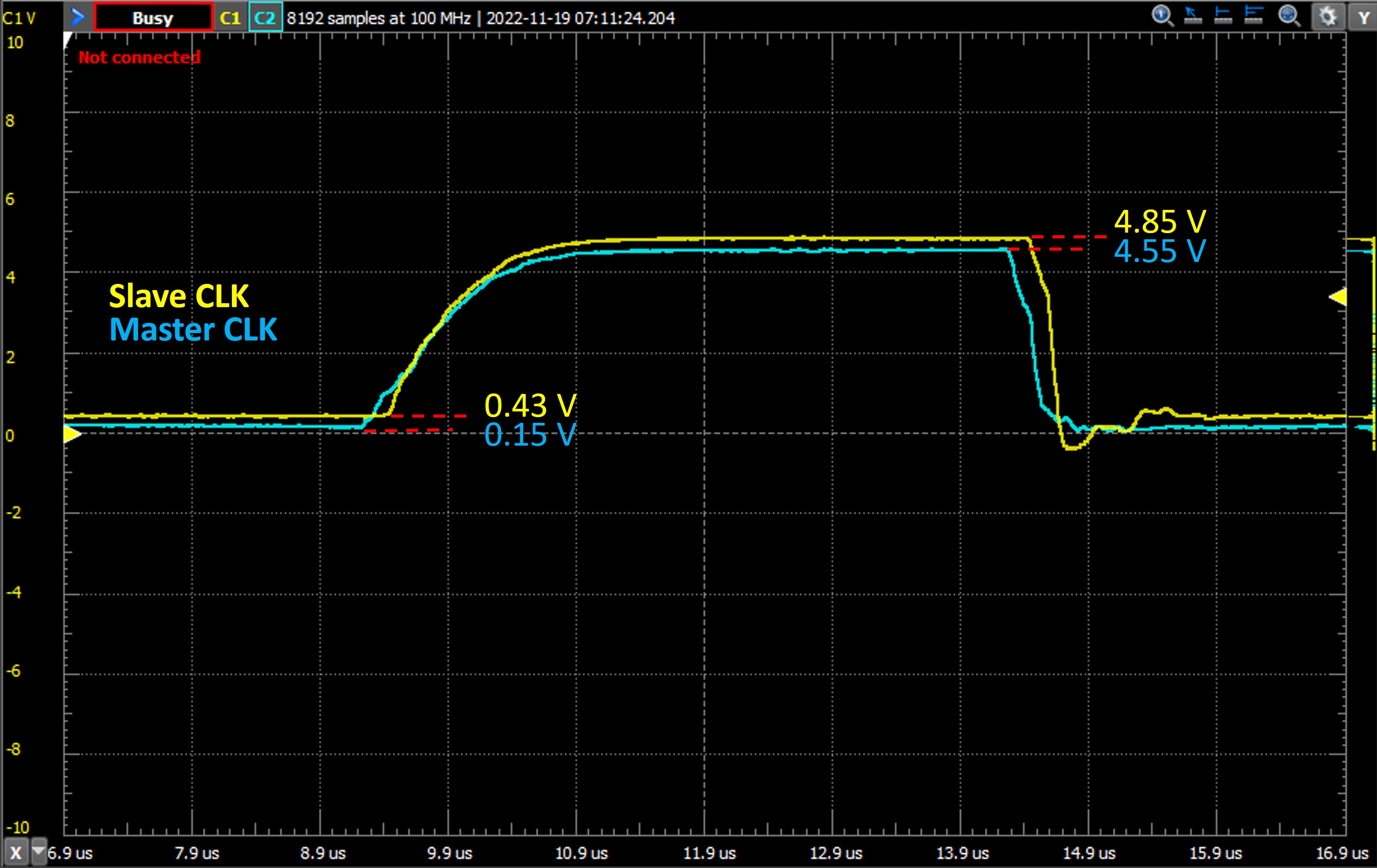
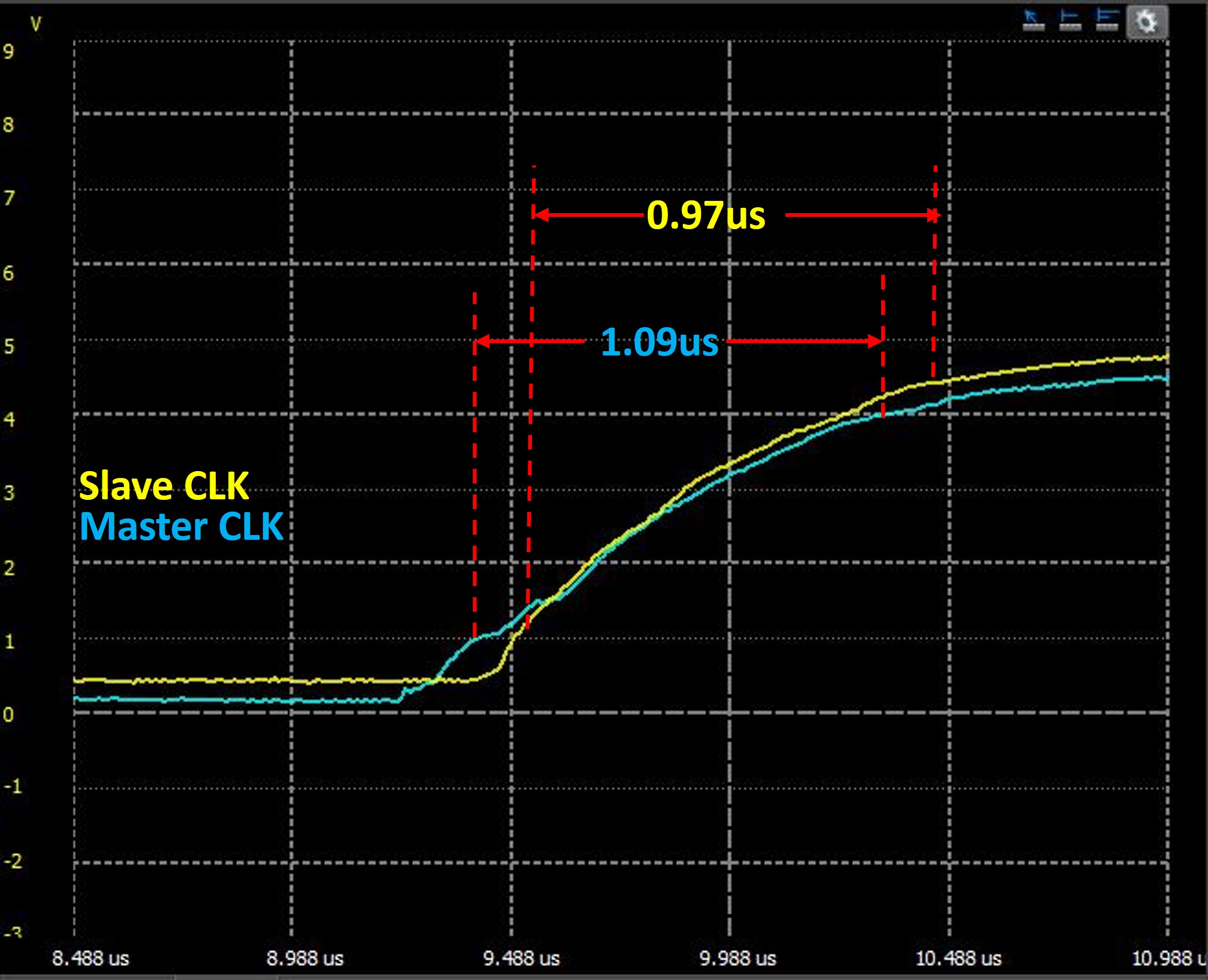
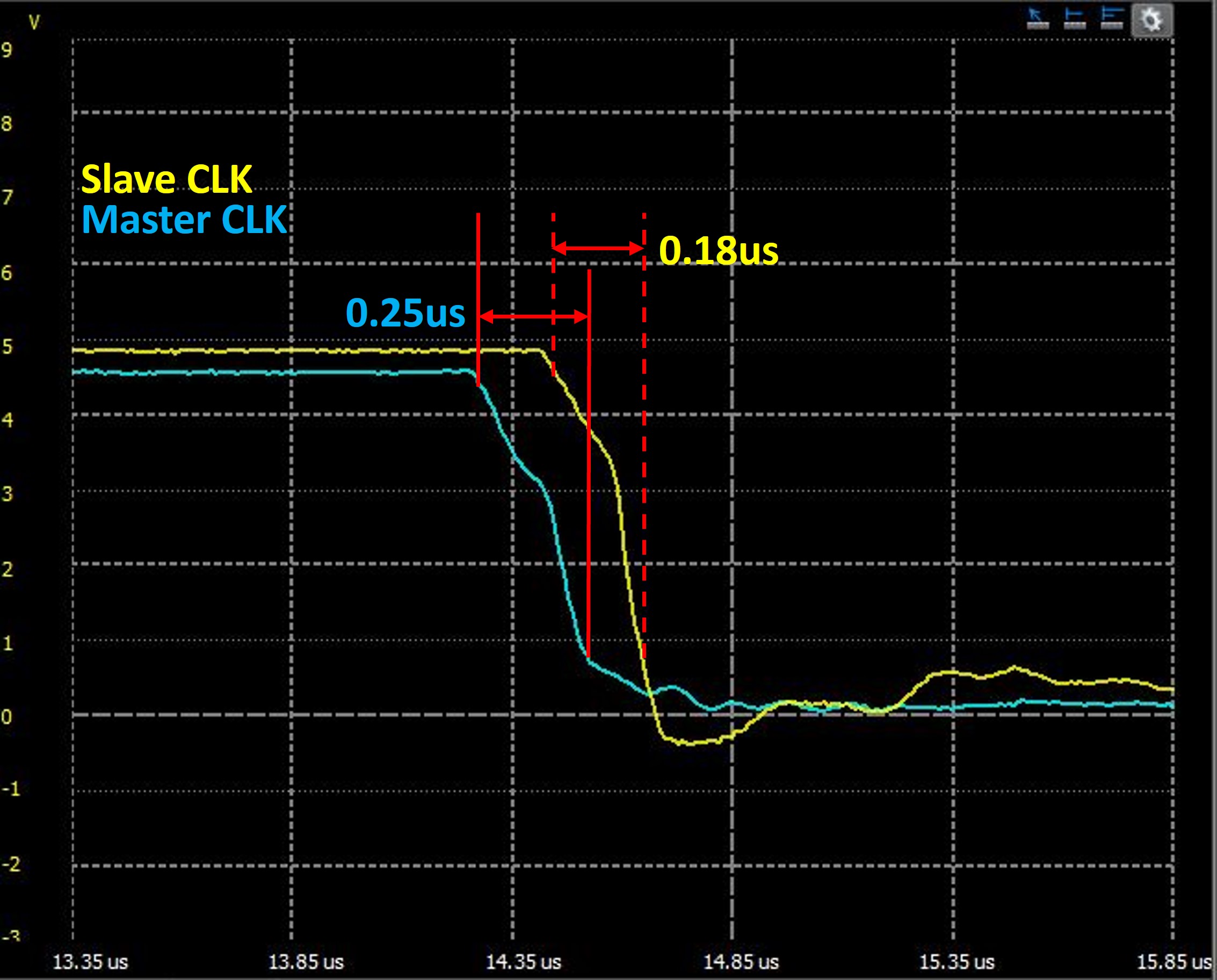
Two buffered cables were constructed using a 10ft and 100ft cat6e cable terminated with the JARViE Extender on both ends (see image in product listing). A 0 to +5V square pulse was generated and sent down each cable using an Arduino Mega 2560 development board. The other end of the cable was loaded with an Arduino Uno development board. An oscilloscope was placed at both ends of the cable to capture what the pulse looked like after traveling from the start/generator side of the cable to the end/load side of the cable. Ideally, the square pulse sent is identical to the pulse received at the other end of the cable. Due to the capacitive, resistive and inductive properties of the cable and development board I/O ports, this was not the case. The signal was distorted, delayed and or smaller in amplitude.
The figures below show,
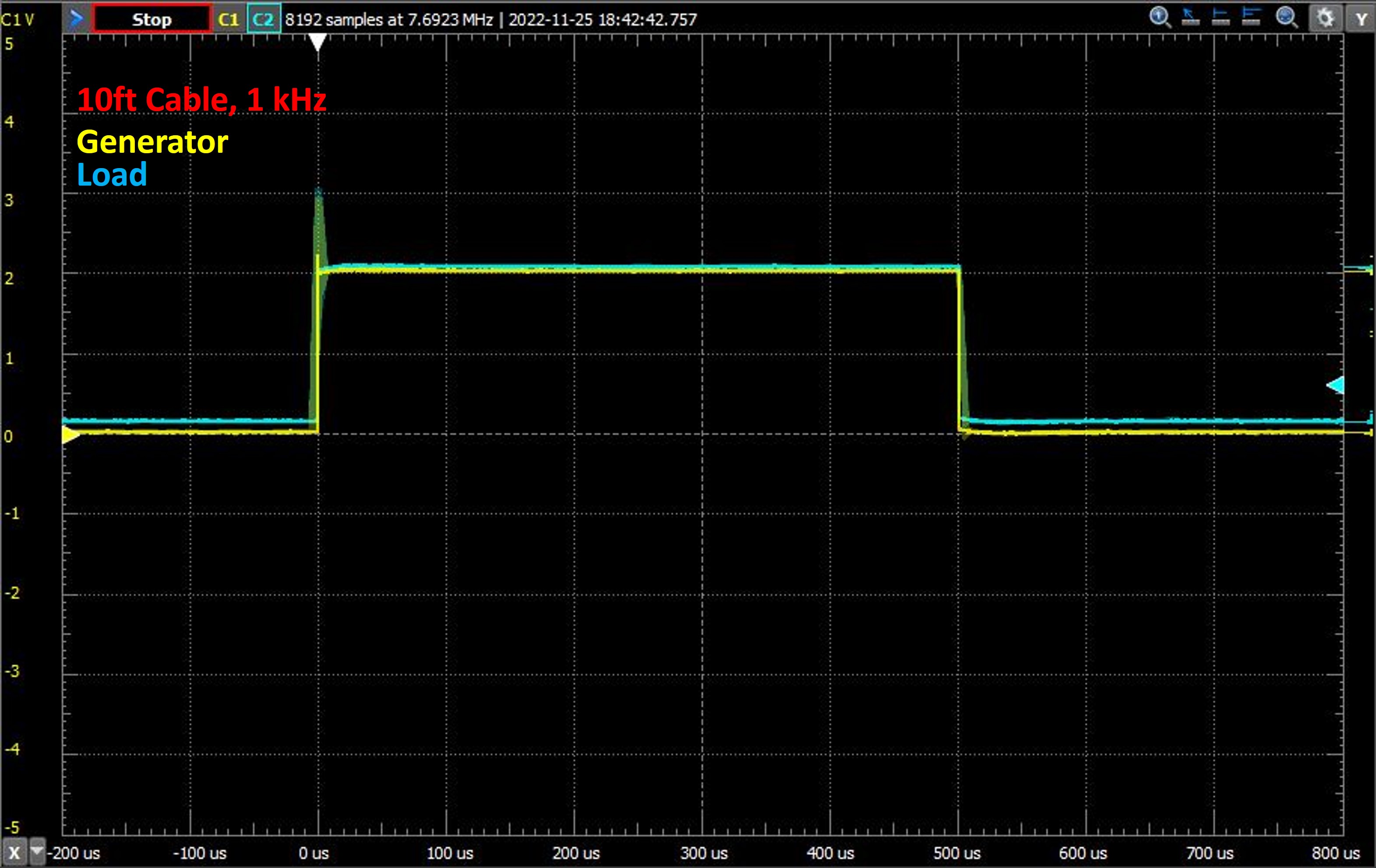
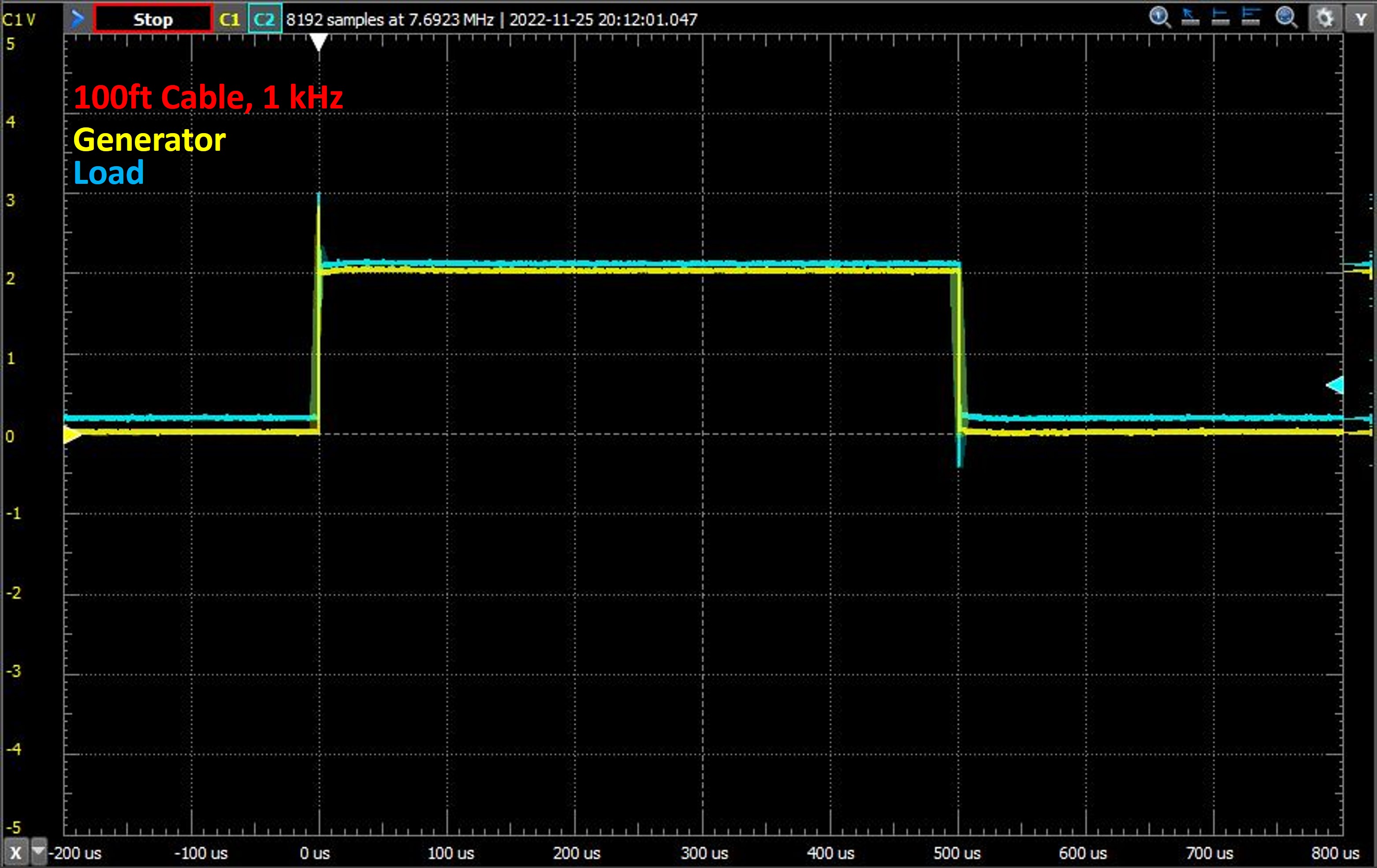
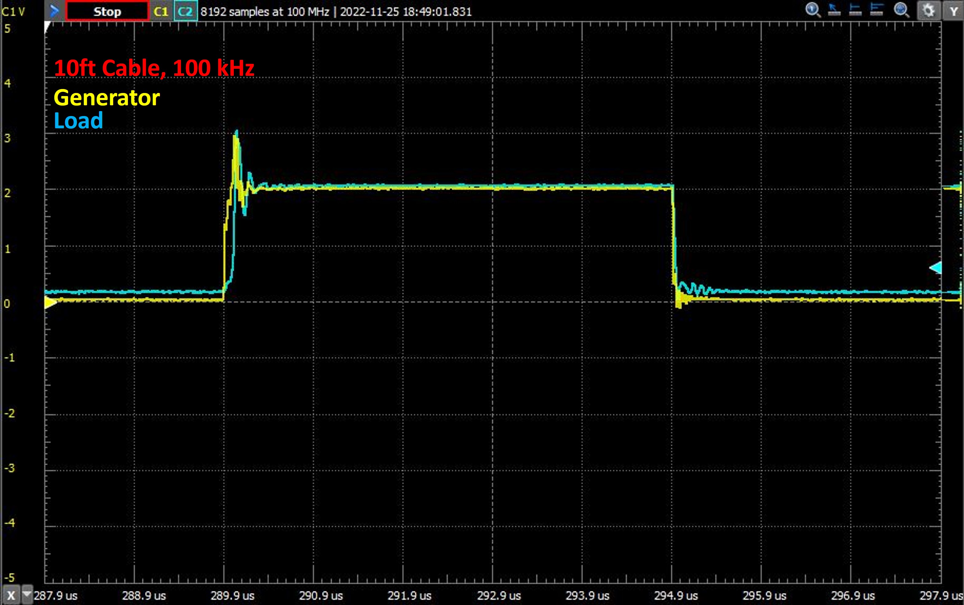
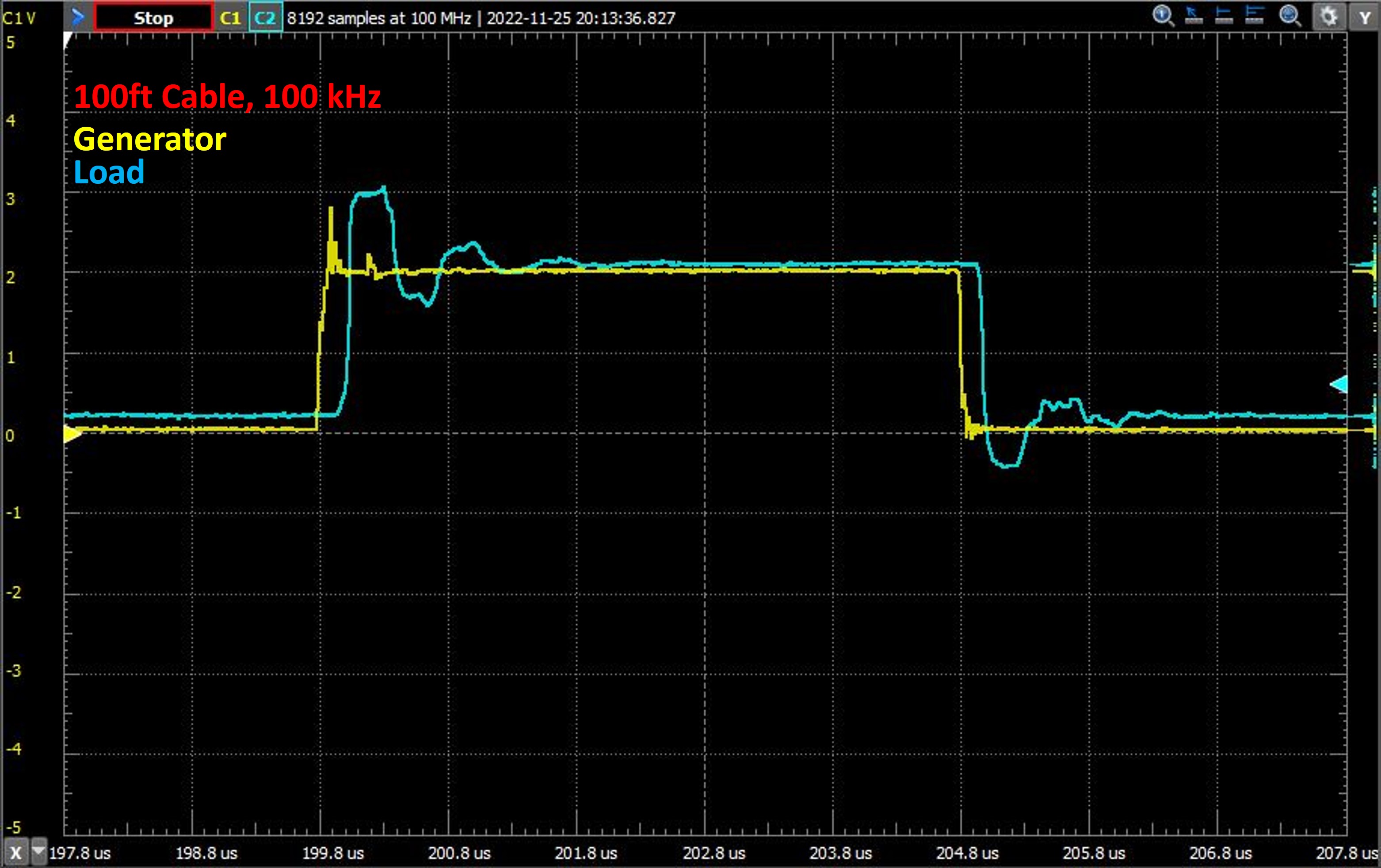
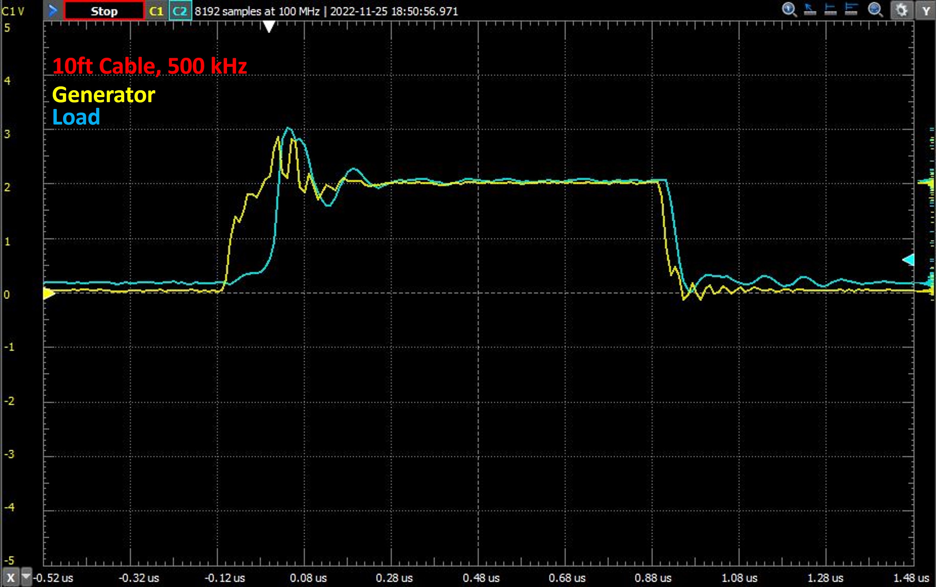
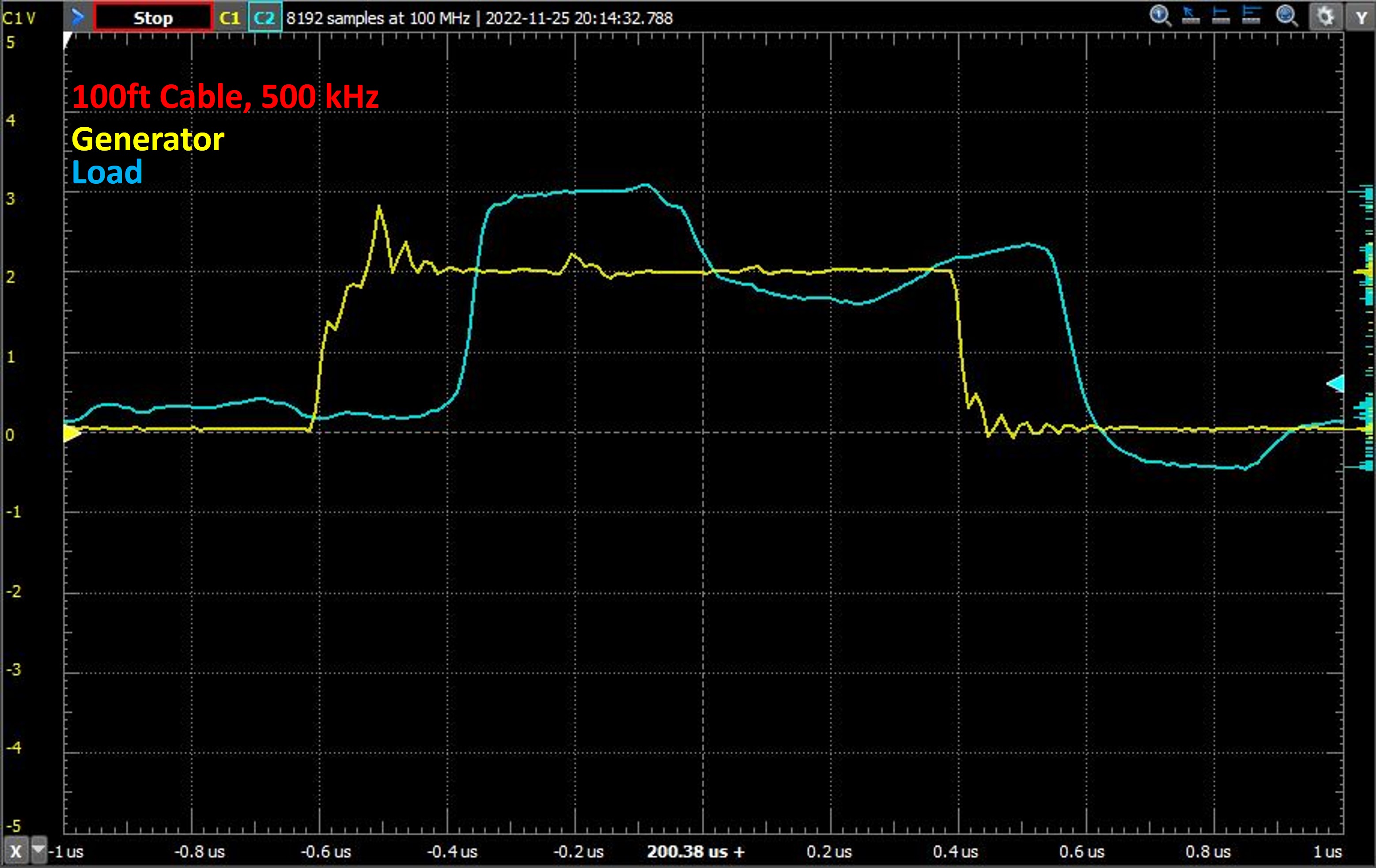
A 1 MHz square wave was driven down a 100ft cat6e cable buffered with a JARViE I2C/SPI/GPIO Extender on both ends. No devices were connected to the load side of the cable, so this is an open load measurement. Here's a scope capture of the square wave received at the load/slave device side of the cable,
An eye diagram was generated by placing the oscilloscope in persistence mode, configuring the scope to trigger on either falling or rising edges and acquiring 12,614 samples. The diagram shows that a 1MHz signal and or communications bus could send data over a 100ft twisted pair cable with minimal noise or high signal-to-noise ratio (SNR) which means less bits being corrupted or dropped, implying good communications.
No country selected, please select your country to see shipping options.
No rates are available for shipping to .
Enter your email address if you'd like to be notified when JARViE Extender - Send I2C/SPI/DIO up to 150ft can be shipped to you:
Thanks! We'll let you know when the seller adds shipping rates for your country.
| Shipping Rate | Tracked | Ships From | First Item | Additional Items |
|---|---|---|---|---|
|
:
|
| Quantity | Price |
|---|---|
| 1 | $20.00 |
| 2+ | $15.00 |
Buy with confidence.
Our Tindie Guarantee protects your purchase from fraud. Learn More
Pflugerville, TX, United States of America
Ships from United States of America.
1 Review | 41 Orders
$70.00
Free Shipping!
$60.00
Free Shipping!
$65.00
Free Shipping!
$185.00
Free Shipping!
$100.00
Free Shipping!
$16.50
Free Shipping!
$5.00
Free Shipping!
By clicking Register, you confirm that you accept our Terms & Conditions
We recognize our top users by making them a Tindarian. Tindarians have access to secret & unreleased features.
We look for the most active & best members of the Tindie community, and invite them to join. There isn't a selection process or form to fill out. The only way to become a Tindarian is by being a nice & active member of the Tindie community!
