4-channel MONSTER MOSFET board - 2.5 Vgs, 20Vds / 5Vgs/100Vds, optional gate driver
Designed by Azduino by Spence Konde in United States of AmericaThis seller is taking a break. Sign up below to get an email when they're back!
No shipping info available.
Set destination country to see options
Shipping to starts at
Free shipping is available to !
Ships from
This item does not ship to .
More Info
Sign up and we'll send a reminder when the seller returns!
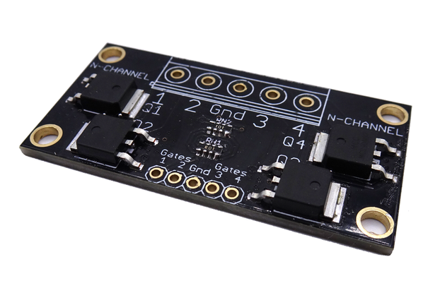
These aren't MOSFETs, these are MONSTER FETs. An extra beefy version of my other MOSFET breakout board - All of these FETs are rated for tens of amps under realistic conditions, and brief pulses of 1…
Read More…These aren't MOSFETs, these are MONSTER FETs. An extra beefy version of my other MOSFET breakout board - All of these FETs are rated for tens of amps under realistic conditions, and brief pulses of 100A or more. The board is designed such that you can fit heatsinks on without blocking the installation of screw terminals, if you need it. Unlike previous iterations, these boards are truly designed to keep pace with the FETs - we have measured the resistance between the holes for the terminal strip and the drain or source of the FETs as 0.6 milliohms. Dozens of thermal vias provide improved heatsinking. Optional gate drivers permit high frequency PWM which would be impossible when driving the gates directly from a microcontroller.
Gate drivers would be needed if PWMing these at more than around 1-2 kHz. See our MOSFET Guide for more information on connections and sizing/selection guidance.
If you need a larger quantity of a version than I have in stock, send me a message and I can have them assembled within a few days; the limited stock is to make sure I don't make piles of an unpopular version, leaving me without parts to build more of a popular version.
This board is manufactured on 2oz copper, with wide traces on both sides to carry both current and to help dissipate heat from the MOSFETs. The board can accept screw terminals on either 0.2" pitch pins - the small green screw terminals readily available from Chinese suppliers - or larger screw terminals on 9.5mm pitch pins. Note that even the larger screw terminals are only available rated up to 40A. Heavier loads require soldering a suitable wire directly onto the board; large exposed pads are provided for that purpose. There are two sets of mounting holes on the top - the one on the tabs (which can be broken off to fit into tight spaces) are for when large screw terminals are used, as they would cover up the other set of mounting holes.
Overall board dimensions are 2" x 2" with the mounting tabs, 2" x 1.75" with them removed.
For the most demanding use cases - specifically high frequency PWM of large loads - we offer a version with a pair of gate drivers; we use the NCP81071B or IX4340 gate drivers - both are of comparable price and performance, and are pin compatible; we added the IX4340 whenwe had trouble sourcing more NCP81071B drivers in mid 2021. These are capable of delivering a brief pulse of surprisingly high current into the gate to rapidly switch the MOSFET on or off, in response to a low voltage input signal: 2.2v or higher, and these will treat it as a HIGH and apply the full supply voltage to the gate of the FET, below 0.8V they will treat as a LOW and ground the gate. This means that you can control the high-voltage versions with 2.5V logic. These require at least 5V on the V+ pin; they can take a voltage as high as 20V without damage (Max. 10V should be supplied to V+ with BSC026N02). The voltage supplied at V+ is the voltage applied to the gate, so with the higher voltage version, providing 10V on V+ will allow for lower on-state resistance (with the BSC026N02, the minimum 5V needed by the driver itself is already high enough that the MOSFET is completely on, with maximum resistance of 2.6 milliohms - your wires will likely have more resistance than the MOSFET).
Where the required current exceeds the specified maximum continuous current without additional cooling, or under heavy loads while PWM'ing the gate at very high frequencies, heatsinks can be used. For almost all loads, you do not need them, though. We offer optional heatsinks; Due to problems with thermal epoxy as well as problems with heatsinks getting knocked off in transit, we are no longer offering installed heatsinks as an option. But do not despair - I've succeeded in sourcing an abundant supply of heatsinks with thermal tape on the back. So now, if heatsinks are selected, you will get a pair of heatsinks with adhesive thermal-transfer tape on the back - simply peel off the backing, line the heatsink up along the edge of the terminal block, and place so that it covers both FETs on one side. Repeat for the other heatsink on the other two FETs. The thermal transfer properties of the tape are not markedly worse than epoxy; the dichotomy is largely "thermal compound and springs to hold it in place" (ie, the solution used for desktop computer CPUs among many other uses) vs "anything else" (assuming the "anything" was designed for heat transfer; I suppose things like double-stick normal tape, or elmers glue would be a third, worst category).
When driving an inductive load (motors, solenoids - anything where there's a coil of wire and this is controlling the current through it), you MUST connect a diode sized to be able to carry the full load of the device between the terminals of the load, with the band towards the positive side (so it normally will not conduct. When the switch is turned off, the current wants to keep flowing, and if you do not include that diode to clamp it, a brief voltage spike up to several times the supply voltage in will be generated; this is great at blowing MOSFETs. These boards do not have any clamping diodes on the board - it would raise costs and complexity (there would need to be a connection to the positive supply as well) they wouldn't really solve the problem for inductive loads: The diode should be located as close to the load as possible. Placing it all the way over on the switching board is both less efficient,and less effective at protecting the rest of the circuit. Ideally, you want the diode directly between the terminals coming out of the inductive load; you will often see this on DC motors not driven by an H-bridge in consumer devices, and all the coils in a pinball machine are wired like that.
Datasheet: BSC026N02 Rds(on): 3.5~4.3 mOhm @ 2.5 Vgs, 2.1~2.6 @ 4.5Vgs Vds: 20V max Current: Approximately 25A per channel without added cooling
Datasheet: BSC082N10LS Rds(on): 8.2~11 mOhm @ 4.5 Vgs, 6.8~8.2 @ 10Vgs Vds: 100V max Current: Approximately 14A per channel without any added cooling - significantly more with.
Note: The BSC082N10LS is marked as "not for new designs" indicating that the manufacturer intends to discontinue it - the best substitute I have found is the DMT10H010LPS, which is not quite as good. I will continue offering these as long as I am able to get them.
Datasheet: DMT10H010LPS Rds(on): 10~20 mOhm @ 4.5 Vgs, 6.9~8.3 @ 10Vgs Vds: 100V max Current: Approximately 9A per channel without added cooling.
No country selected, please select your country to see shipping options.
No rates are available for shipping to .
Enter your email address if you'd like to be notified when 4-Channel MOSFET board with optional driver can be shipped to you:
Thanks! We'll let you know when the seller adds shipping rates for your country.
| Shipping Rate | Tracked | Ships From | First Item | Additional Items |
|---|---|---|---|---|
|
:
|
International orders have been suffering long delays due to COVID-19 - please check your country at https://about.usps.com/newsroom/service-alerts/international/ and make sure that I can ship to you, and that you are okay with any delays. There may be additional information available from your national postal service. Some customers have reported packages being delayed in transit by over a month. We cannot offer any sort of guarantees regarding international shipments at this time; we apologize for the inconvenience, and are looking into shipping internationally through UPS.
Please be sure that the address given to Tindie is accurate, and includes your street name and number - company name is only required if shipping to a commercial address. International orders require a valid phone number.
Domestic packages that go more than 1 week without a tracking update will be presumed lost in the mail and refunded or reshipped as buyer prefers. Any international packages can be delayed in customs without warning for 2 weeks or more. After 1 month without a tracking event (2 months to South and Central America - insane delays in those nations are commonplace), we will reship or refund a missing order (as you prefer). COVID-19 update: Some countries have stopped processing incoming international mail entirely -we will cancel orders to countries which we know are not processing international mail at all. This may also cause longer than usual shipping times - we are not responsible for such delays.
We do not open inquiries through the postal service - experience has shown this to be futile.
We ship all orders via USPS. UPS will be added as an option in the near future, I hope. We do all shipping through Stamps.com, and they offer me UPS, but all addresses are rejected as invalid, and I have emailed support numerous times and have had zero response. So at present, we cannot entertain requests to ship through other carriers.
Product: (5.00)
Documentation: (4.25)
Shipping: (4.50)
Communication: (5.00)
William | June 9, 2022
Brittani | April 22, 2018
Joe | Feb. 24, 2018
Josh | April 15, 2016
No shipping info available.
Set destination country to see options
Shipping to starts at
Free shipping is available to !
Ships from
This item does not ship to .
More Info
Sign up and we'll send a reminder when the seller returns!
somerville, MA, United States of America
Ships from United States of America.
120 Reviews | 2,333 Orders
$3.95
Free Shipping!
$1.70
Free Shipping!
$13.00
Free Shipping!
$5.00
Free Shipping!
$5.50
Free Shipping!
$37.00
Free Shipping!
$3.00
Free Shipping!
$8.00
Free Shipping!
$15.00
Free Shipping!
$3.25
Free Shipping!
$14.59
Free Shipping!

$13.00
Free Shipping!
By clicking Register, you confirm that you accept our Terms & Conditions
We recognize our top users by making them a Tindarian. Tindarians have access to secret & unreleased features.
We look for the most active & best members of the Tindie community, and invite them to join. There isn't a selection process or form to fill out. The only way to become a Tindarian is by being a nice & active member of the Tindie community!
