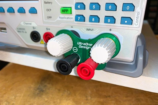
Monsieur Adaptateur is an adapter which adapts between different plug formats you'll encounter when prototyping circuits on 2 channels.
Designed by felitek.de in Germany
This product is no longer available for sale.
The seller may be offering an improved version or it may be hanging out on the beach, enjoying the retired life.

$29.99
Free Shipping!

$3.50
Free Shipping!

$48.00
Free Shipping!

$159.00
Free Shipping!
Introducing Monsieur Adaptateur Monsieur Adaptateur is an adapter which adapts between different plug formats you'll encounter when prototyping circuits on 2 channels. Using Monsieur Adaptateur, you …
Read More…Monsieur Adaptateur is an adapter which adapts between different plug formats you'll encounter when prototyping circuits on 2 channels.
Using Monsieur Adaptateur, you can interconnect the following standard connectors:
Other case colors than black are sold out, sorry!
Assembly is pretty easy, you only need a soldering iron, a wrench for the banana jacks (pliers would also work) and a Philips screwdriver. I also made assembly instructions, see on the right-hand side (documentation link).
The upper half of the PCB is the first channel (usually GND) and the lower half is the second channel (usually positive or negative signal).
The rings of the BNC and DC connectors are connected to the first channel. That's the most common usage - however, sometimes manufacturers put positive voltage on the outer ring on the DC connector.
Application ideas (besides the obvious):
I usually ship out within 1-2 working days. I assemble units in advance, however, please allow up to 2 additional days if there's a rush.
The delivery time within Germany is usually 1-2 working days. Worldwide delivery depends on the destination country. Deutsche Post claims a delivery time of 2-3 working days, however, this could increase if the parcel gets stuck at customs. Also expect to pay customs if you're outside of the EU (this is usually handled by your customs agency).
Initially I wanted to do that, however, I've found that the 5mm screw terminals often lose cables with smaller diameter (I usually use 0.14mm²/26AWG). The screw terminals I use now support up to 1.5mm²/16AWG, which is also about the maximum I ever used for prototyping.
The maximum rated voltage for the whole board is 12VDC, because that's what the DC connector is rated at. If you buy a kit, you may decide to skip the DC connector in order to gain more safety at higher voltages. The PCB itself has an isolation gap of 1mm, which is fine for higher voltages - I recommend a maximum of 30V DC without the DC connector, so bad things won't happen if you touch the contacts. But again, I am not liable if you exceed my recommendations. See the documentation link for a full list of all connectors with their voltage/current ratings.
I thought so, too, until I realized that it wasn't the connectors - it was my multimeter probes, which were only 1.85mm in diameter! My authentic fluke multimeter probes were 1.99mm in diameter, and those where a good fit.
Product: (5.00)
Documentation: (4.75)
Shipping: (4.00)
Communication: (5.00)
Rémi | April 19, 2015
Nathan | April 1, 2015
Christoph | Sept. 19, 2014
Gordon | July 20, 2014
Zbigniew | July 6, 2014
William J | April 23, 2014
Greg | April 22, 2014

$134.99
Free Shipping!

$21.00
Free Shipping!

$30.00
Free Shipping!

$13.96
Free Shipping!
By clicking Register, you confirm that you accept our Terms & Conditions
We recognize our top users by making them a Tindarian. Tindarians have access to secret & unreleased features.
We look for the most active & best members of the Tindie community, and invite them to join. There isn't a selection process or form to fill out. The only way to become a Tindarian is by being a nice & active member of the Tindie community!
