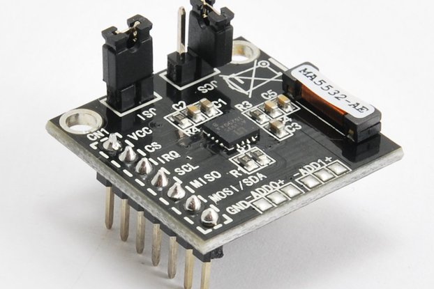
Based on the Bosch BMX055, this sensor board provides a 9 degree-of-freedom inertial measurement solution in the neoPLC form factor
Designed by ag in United States of America
This product is no longer available for sale.
The seller may be offering an improved version or it may be hanging out on the beach, enjoying the retired life.
NeoPLC 9-DoF IMU Board Based on the Bosch BMX055, this sensor board provides a 9 degree-of-freedom inertial measurement solution in the neoPLC form factor. Adjustable full-scale range and Internal fi…
Read More…Based on the Bosch BMX055, this sensor board provides a 9 degree-of-freedom inertial measurement solution in the neoPLC form factor. Adjustable full-scale range and Internal filters make this sensor a great choice for most common IMU needs. Easily adjustable internal filters ensure the data this module outputs are immediately useful – no need to compute filtered data on your microcontroller. The accelerometer has an adjustable range from +/-2 Gs to +/- 16 Gs, and with bandwidth to 1000 Hz. The gyroscope has an adjustable range from +/-125 deg/s to +/- 2000 deg/s, and with bandwidth to 500 Hz. The magnetometer outputs data at up to 30 Hz.
First, provide the neoPLC boards a common ground (GND) and a power bus V+ (anything from 3-5V for all our boards!). Secondly, i2c uses two lines to communicate – a ‘Serial CLock’ (SCL) bus and a ‘Serial Data’ (SDA) bus. Simply connect these to the appropriate pins on your microcontroller and neoPLC board, and you’re all set. Can’t be much easier than 4 wires! One more, very important thing – you must connect a ‘pullup’ resistor (between 1kOhm and 5kOhm) between the SCL and SDA bus. GND, V+, SCL, and SDA are clearly labeled on all neoPLC boards. The SCL and SDA pins on common microcontrollers are listed in the table below:
| SDA | SCL | |
|---|---|---|
| Arduino UNO | A4 | A5 |
| Teensy 3.X | A4/18 | A5/19 |
| Arduino Micro | 19 | 18 |
| Arduino Pro Mini | PC4 | PC5 |
| Arduino Feather | 3 | 2 |
| Arduino Mega | 20 | 21 |
One of the key benefits of the neoPLC boards is the simple wiring. Nearly all modern microcontrollers include a dedicated i2c (pronounced ‘eye-squared-see’) port. Standing for ‘inter-integrated-circuit’, i2c is clever as allows many integrated circuits to share the same communication and power lines – the ‘bus’. The SCL clock is controlled by your microcontroller, it provides a steady march of pulses while communicating to ensure no data is missed by either component. While the SCL steadily pulses, the microcontroller and neoPLC board take turns sending and receiving data over the SDA bus. Each board has a name in i2c called its ‘slave address’. When the microcontroller sends a specific board’s name out on the SDA bus, that board alone will respond. So, many boards can share the same SCL and SDA bus, but only if they have unique addresses – otherwise everyone gets confused about who should be speaking! To allow multiple identical boards on the same bus, we provide adjustable address ‘pads’ on most boards: by cutting the same trace near A0,A1,etc. and putting a small dab of solder on the other side of the pad, the address is changed. Multiple combinations of cut/uncut traces allows several boards to be connected.
Datasheet and library is available in the Right Sidebar. Library was derived from code by Kris Wiener.

$9.50
Free Shipping!

$4.00
Free Shipping!

$15.00
Free Shipping!

$23.00
Free Shipping!
By clicking Register, you confirm that you accept our Terms & Conditions
We recognize our top users by making them a Tindarian. Tindarians have access to secret & unreleased features.
We look for the most active & best members of the Tindie community, and invite them to join. There isn't a selection process or form to fill out. The only way to become a Tindarian is by being a nice & active member of the Tindie community!
