A parts kit to add USB-C charging to the 2DS (original), supports USBC to USBC charging
Designed by BronxDIY in United States of America
Buy with confidence.
Our Tindie Guarantee protects your purchase from fraud. Learn More
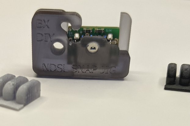
UPDATED: Now the jig is a slip-on resin piece, there's a second version of the 2DS motherboard with an integrated wifi chip and new PCB shape. I provide a jig for both the A and B versions of the mot…
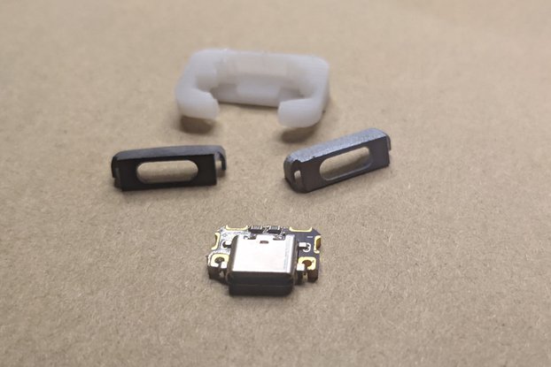
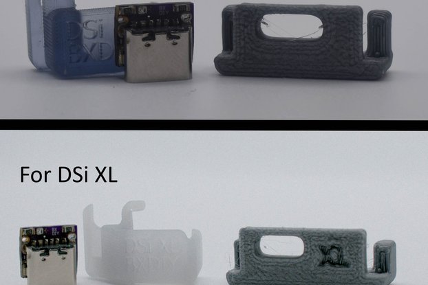
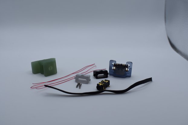
Read More…UPDATED: Now the jig is a slip-on resin piece, there's a second version of the 2DS motherboard with an integrated wifi chip and new PCB shape. I provide a jig for both the A and B versions of the motherboard, refer to the pictures to see which one your motherboard is and which jig you should use. Both are included so you don't have to disassemble your 2DS and fiddle with ordering the right jig.
This is a PCB USB-C charging port to replace the original charging port on the Nintendo 2DS (original only), this port works with USB-C to USB-C cable charging so you don't need to worry about having a USB to USB-C cable.
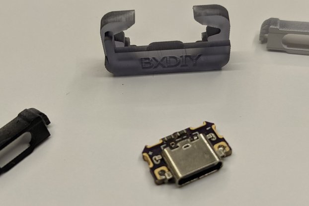
The Installation jig allows you to solder down the board while holding the PCB in perfect alignment, I recommend a little square of folded up cloth to protect your thumb from the heat that the USB-C module will soak up.
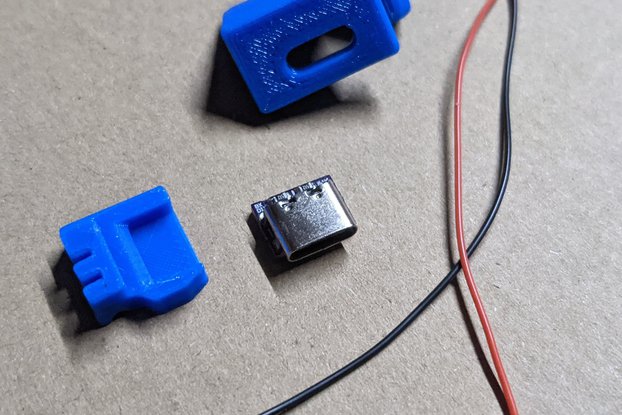
The top midplate needs to be cut/filed to fit the usb-c cord a guide and lock is provided to guide your cutting, I personally use a small handheld grinding pen (rotary tools/engraving/etching pens are a close match) but you might be able to pull it off with rounded files. To prevent flexing of the top faceplate you need to file/grind the back of the power port on the top midplate (refer to the provided picture), do so very carefully.
In testing I get ~5.1 V and ~.58A while charging.
Here is my installation process:
Disassemble your 2DS, be very mindful of the two rods and springs, and keep the top midplate screws separate from the rest as they are shorter than the other screws.
Remove the PCB.
Add flux to the original charging port and with an iron add 63-37 solder to the pads off the charging port (top and bottom) to make it easier to remove.
Use a hot air station @290C (no more than 30-40 seconds is necessary) to remove the original charging port (preheat the board with a hot plate @168C or use the hot air station to preheat the board)
Clean the PCB pads, and use solder wick to remove the old solder. Re-solder the pads and of the two port pins/pads I would ignore the ground pad and add a small bit extra to the power/5v pad (the 5v is the one of the two that is closest to the game cartridge slot).
Identify your motherboard version (A or B refer to the pictures, B has an integrated wifi chip and A has a removable wifi module and antenna). Slide the appropriate resin jig on the charging port area, lining it up with its cutouts (refer to the pictures).
Place PCB into the jig, and then check alignment of the jig the bottom pads should be surrounded by the jig but not touching it.
Apply some flux to bottom pads
From the bottom use a decent amount of solder to the affix the board, I have my iron at 295C for this and I rotated my iron between all the pads. During this step I use a folded bit of cloth to insulate my thumb from the heat of the USB-C port so I can get away with pressing it flat it's an optional approach.
There are two holes/vias on the top of the USBC board add a small bit of flux to them and then with a small iron (just small enough to avoid touching other pads) add solder and fill these holes to affix the top of the board to the PCB.
(optional) This is especially useful if you're having connecting the 5v pad, there's a via above the 5v pad next to the + sign on the USBC board and with a small iron tip and steady careful hands you can directly heat the via and pad and affix the 5v pad.
Use a multimeter to make sure that 5v/VCC isn't shorted to GND and check the you've connect 5v and GND to the USBC board. Ground/GND can be tested right off the shield (the shell of the USBC port) of the USBC board and any GND point on the PCB (like the game cartridge slot). 5v/VCC can be found on the PCB on the back between the 4 GND pads/vias or on the front on the fuse and can be checked against pins 2 and 5 (B9/A9) on the USBC board and the via in the top left corner or the via above pin 2 (B9).
Use flush cutters to cut the notch of the resin jig and slide it off the PCB (the PCB should be relatively cool/room temperature to avoid bending it). Refer to the pictures.
Check that the board is flat to the pcb and the edge of the board should line up with the edge of the pcb (with the usb-c port hanging over it).
Double check that there's no short between 5v/VCC and GND with your multimeter and then plug a USB-C charging cable into the USB-C port, if everything's 'wired' correctly you should see an orange light come on on the PCB (even though nothing else is attached).
SANDING/FITTING
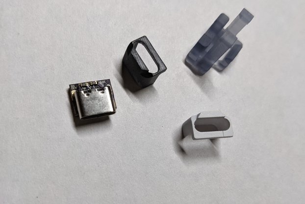
Put the cutting jig through the charging port on the top midplate (the correct orientation is shown in the pictures on the listing).
Put the lock for the cutting jig over the the extended portion of the cutting jig (correct orientation is shown in the pictures on the listing) press down until you have a nice snug fit you just need the cutting jig held in place.
Use a grinder or file to cut out the the slot for the usb-c cable to enter. You've cut enough when you can see the USB-C port and there's nothing blocking it, you'll need to disassemble the jig to check.
Grind or file down the back of the port you just cut out. Do not overdo it just a light pass at first. Refer to the pictures to see the portion to grind/file I'm talking about.
Place the bezel on the USB-C port and place the PCB board on top of the bottom half of the nintendo 2ds (you don't need to connect any cables we're just checking fit).
Put the top midplate back on, and check for flex it's easy to see if you screw it in however a faster way is to check the left hand screw hole (one under the right trigger) that holds down the top midplate if the top midplate screwhole is excessively offcenter from the face plate screw hole you'll know it will flex. Make sure to double check that the bezel is fitted correctly and cleared through the charging port hole of the top midplate.
Keep going through steps 20 and 19 until a good fit is achieved.
Assemble your device you’re done.
All in all I’d say it’s a moderately difficult job not to especially hard but the filing and checking can get tedious.
REQUIRED BUT NOT INCLUDED TOOLS:
(highly) RECOMMENDED BUT NOT INCLUDED TOOLS:
INCLUDED:
No country selected, please select your country to see shipping options.
No rates are available for shipping to .
Enter your email address if you'd like to be notified when 2DS USB-C mod kit w/ snapjig+bezel can be shipped to you:
Thanks! We'll let you know when the seller adds shipping rates for your country.
| Shipping Rate | Tracked | Ships From | First Item | Additional Items |
|---|---|---|---|---|
|
:
|
Buy with confidence.
Our Tindie Guarantee protects your purchase from fraud. Learn More
$12.00
Free Shipping!
$12.00
Free Shipping!
$12.00
Free Shipping!
$12.00
Free Shipping!
$12.00
Free Shipping!

$12.00
Free Shipping!
$12.00
Free Shipping!
$20.00
Free Shipping!

$12.00
Free Shipping!

$12.00
Free Shipping!

$12.00
Free Shipping!

$12.00
Free Shipping!
By clicking Register, you confirm that you accept our Terms & Conditions
We recognize our top users by making them a Tindarian. Tindarians have access to secret & unreleased features.
We look for the most active & best members of the Tindie community, and invite them to join. There isn't a selection process or form to fill out. The only way to become a Tindarian is by being a nice & active member of the Tindie community!
