A parts kit to add USB-C charging to the DS LITE, supports USBC to USBC charging
Designed by BronxDIY in United States of America
Buy with confidence.
Our Tindie Guarantee protects your purchase from fraud. Learn More
UPDATED: It's now a slip on resin jig This is a PCB USB-C charging port to replace the original charging port on the Nintendo DSL, this port works with USB-C to USB-C cable charging so you don't need…
Read More…UPDATED: It's now a slip on resin jig This is a PCB USB-C charging port to replace the original charging port on the Nintendo DSL, this port works with USB-C to USB-C cable charging so you don't need to worry about having a USB to USB-C cable.
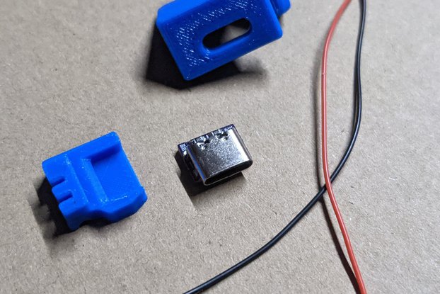
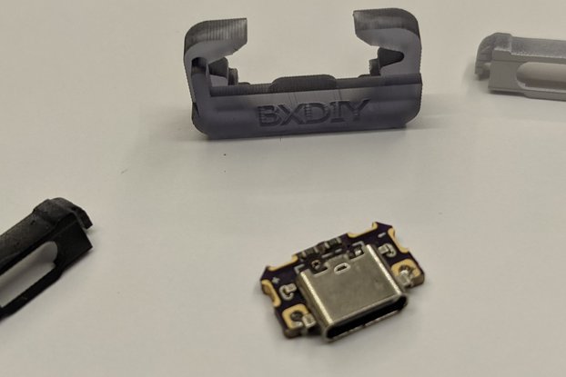
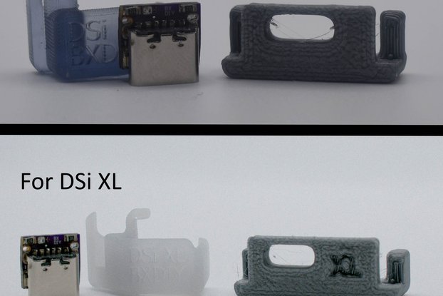
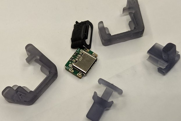
The Installation jig allows you to solder down the board while holding it in alignment, two thumb screws are provided for easy assembly and disassembly of the jig.
Due to the heat of the iron I consider the jig to be a single use item but I've started printing them out of ASA for greater thermal resistance.
Here is my installation process:
BOARD INSTALLATION 1. Disassemble your Nintendo DS Lite, be very mindful of the trigger springs and rods
Remove the PCB.
Use a hot air station @290C (no more than 30-40 seconds is necessary) to remove the original charging port (preheat the board with a hot plate @168C or use the hot air station to preheat the board)
4 Optional. Clean the PCB pads, and use sand paper or a rotary too to expose the top most trace (it's the one nearest to the edge). Add solder to this exposed trace, it will melt into the USB-C receptacle making a stronger hold
Place the USBC board into the resin jig (if not already in there) and then firmly slip the jig onto the PCB there is a silk screen square around the component next to the fuse (the component circled in red in the pictures) try to line up the edge of the USBC board with that to give you a good idea if it's on straight.
Turn the PCB board over and apply flux to the holes.
Use a decent amount of solder to the affix the board. I have my iron at 295C for this and I rotate between all of the pads/holes to make sure a decent of amount of solder flows through.
Use a multimeter to test GND (-) and VCC(+) make sure that they're not shorted and that you have good connections between PCB GND and USBC board GND and the same for VCC.
After continuity testing you'll need to snip the curled arm on the resin jig so that you can properly remove the resin jig (I use flush cutters).
SANDING/FITTING 1. Set aside any loose plastic parts from the bottom half of your DS lite so you don't lose them.
The USB-C receptacle hangs over the motherboard (expected) however the tips of the USB-C board hang over the motherboard as well and they cause interference with the bottom half of the DS lite. I use flush cutters to nip off the majority of it. Now you have a decision to make either grind it away with a rotary tool or file so it's flush with the motherboard (the board not the receptacle) or do the filing on the bottom half of the DS lite (I HIGHLY recommend you do the latter the amount of filing of the USBC board is obscene and there will be metal dust everywhere). The filing on the bottom half of the DS lite would need to be done on the inner side of the wall directly on the left and right of the charging port cutout (essentially thinning that section of the wall).
Look at the screwhole/post to the immediate left of the charging port section of the bottom half of the ds lite, you will need to cut the raised portion. The depth of your cut should be to the flat part of the screw hole and it should encompass half of the circular flange (look at the photos to see it).
You will need to cut down the raised walls that secure the old charging port in the bottom half of the DS lite, the walls will have to be cut down to the height of the charging port cutout (refer to the photo in the listing but you don't need to totally remove the right wall like I did.
Now we'll check for the clearance of the USB-C receptacle, take the motherboard and place it in the bottom half of the DS lite and see if the USB-C receptacle slides into the charging port cutout, if it's too snug lightly file the sides of the cutout.
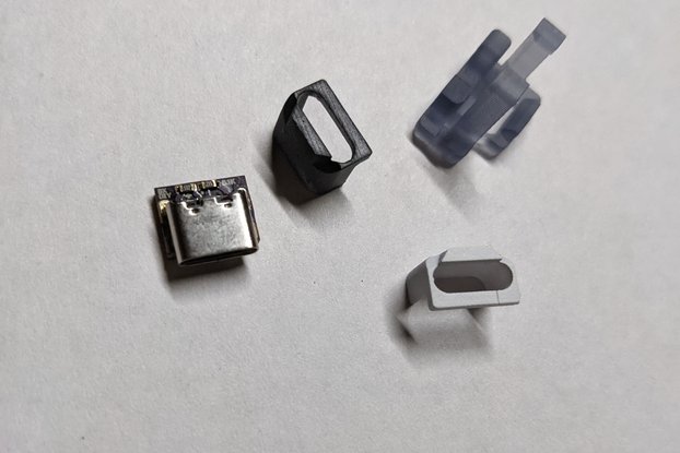
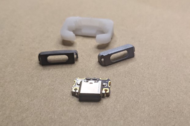
Take the bezel and fit it into the three hole section of the charging port section of the bottom half of the DS lite it should fit easily and then place the motherboard in the bottom half of the DS lite to check for fit. Sand and file down any obstructions until you have a good fit.
NOTE: The orange light flashes off if no battery is detected, to test the mod without reassembling the whole thing place the motherboard in the bottom half of the case and place a battery in before testing a usb-c cable.
The sanding is the hardest part.
REQUIRED BUT NOT INCLUDED TOOLS:
(highly) RECOMMENDED BUT NOT INCLUDED TOOLS:
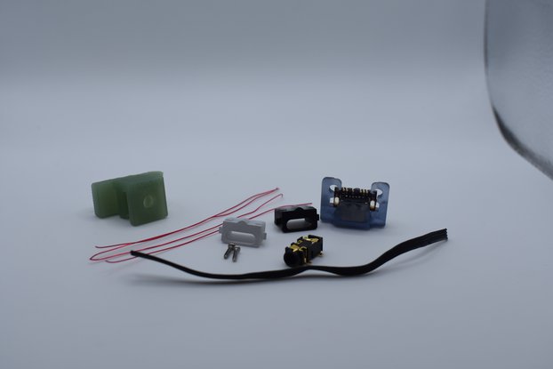
INCLUDED:
No country selected, please select your country to see shipping options.
No rates are available for shipping to .
Enter your email address if you'd like to be notified when DS Lite USB-C mod kit w/ snapjig+bezel can be shipped to you:
Thanks! We'll let you know when the seller adds shipping rates for your country.
| Shipping Rate | Tracked | Ships From | First Item | Additional Items |
|---|---|---|---|---|
|
:
|
Buy with confidence.
Our Tindie Guarantee protects your purchase from fraud. Learn More
$12.00
Free Shipping!
$12.00
Free Shipping!
$12.00
Free Shipping!
$12.00
Free Shipping!

$12.00
Free Shipping!
$12.00
Free Shipping!
$20.00
Free Shipping!
$12.00
Free Shipping!

$12.00
Free Shipping!

$12.00
Free Shipping!

$12.00
Free Shipping!

$12.00
Free Shipping!
By clicking Register, you confirm that you accept our Terms & Conditions
We recognize our top users by making them a Tindarian. Tindarians have access to secret & unreleased features.
We look for the most active & best members of the Tindie community, and invite them to join. There isn't a selection process or form to fill out. The only way to become a Tindarian is by being a nice & active member of the Tindie community!
