A parts kit to add USB-C charging to the GBA SP and audio jack, supports USBC to USBC charging
Designed by BronxDIY in United States of America
Buy with confidence.
Our Tindie Guarantee protects your purchase from fraud. Learn More
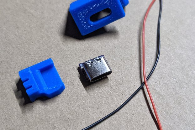
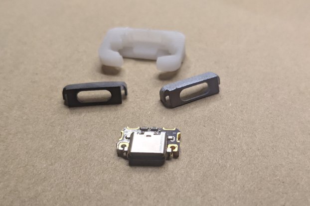
This is a PCB USB-C charging port to replace the original charging port on the GBA SP, this port works with USB-C to USB-C cable charging so you don't need to worry about having a USB to USB-C cable.…
Read More…This is a PCB USB-C charging port to replace the original charging port on the GBA SP, this port works with USB-C to USB-C cable charging so you don't need to worry about having a USB to USB-C cable. An audio jack and wires are provided to do an audio jack mod. This kit does not provide audio over USBC instead audio is gained by wiring up an audio jack, you can't use USBC-3.5mm jacks with this mod.
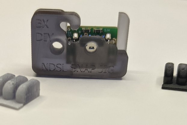
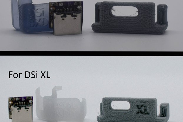
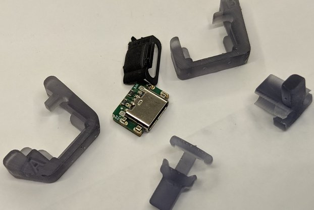
The Installation jig allows you to solder down the board while holding the PCB in perfect alignment
It bears saying that kapton tape or heat shrink tubing are essentially necessary for this mod to prevent a short between the audio jack and the motherboard.
Here is my installation process:
SOLDERING
Disassemble your GBASP to remove the motherboard, it's not strictly necessary to remove the left and right shoulder buttons but seeing as you will be cutting a hole in the GBA SP it is highly recommended that you remove them and safely store them as they will probably come out during the mod.
With the motherboard removed apply flux to the old charge port and remove it with a soldering iron or heatgun.
With the charge port removed use soldering braid to wick up excess solder from the pads, do so slowly and carefully you don't want to lift pads. Throughout the whole process your soldering iron doesn't ever need to be hotter than 300C.
Place the diy USBC kit board into the resin snapjig slip the snapjig onto the motherboard push in firmly but carefully and check that the holes and pads are all lined up with each other.
Apply flux to the big through hole pads on the sides of the kit board, then solder them in with your iron. I like to apply enough solder that some droops through the motherboard to the other side, if you apply heat for too long a big glop of solder can fall through so there's no need to be excessive.
Apply flux the the tiny pads along the top of the kit board and then solder them all in place.
Take out your multimeter and make sure none of pads on the top row are connected (0 ohm, continuity test beep) as none of them should be. Snap the arms of the jig and remove it.
Choose which wire you would like to use, the black stranded wire or the red magnet wire, either is fine but it is harder to obtain a good fitting assembly with the black wire since they are so thick but magnet wire can be difficult to work with.
Before you can wire up the audio jack you will need to cut out a hole for it, please move on to the grinding/filing stage.
CUTTING THE HOLE GRINDING AND FITTING
Take the resin cutting jig and with the internals of the backplate of the GBA SP facing you and the shoulder button are on the top place the cutting jig in the top right corner. The circuler peg should fit in a corresponding open peg on the GBA SP backplate.
With the jig firmly in place to increase its stability you can flip the backplate over and so that the open battery cavity is facing you and gently screw the provided screw through the screw hole where the cutting jig is placed. The cutting jig has threading but resin is very brittle so do be careful while screwing in and stop immediately after it feels snug (overtightening it will strip everything and make the whole thing a nightmare).
Turn the backplate so the hole of the jig faces you, if you try to place the audio jacks open port into the hole you'll notice that it won't fit as the hole is undersized. Also if you look closely you will see four ridges on the internals of the hole, these mark the spot where you should slow your cutting or grinding.
With your preferred cutting/sanding tools cut through the cutting jig hole and make a hole in the backplate for the audio jack. You can use the audio jack as a test fit to see if you've cut enough material if it fits very tightly you can remove the cutting jig and free hand the rest of the cut slowly checking back frequently with the audio jack to see if your hole is wide enough yet.
Remove the flashing created by your cutting on the inside of the backplate.
We will now need to remove a bit of internal material starting with the screw hole peg on the upper middle of the backplate as it comes right down onto the kit board. You will need remove the right half of it so that the kit board can fit, refer to the photo in the listing.
Angle the audio into it's hole and make note of the obstructions to it laying flat, snip and file away the obstructing bits of plastic until you can lay the audio jack down with it fitting through the hole you made in the backplate. Refer to the images in the listing to see what I cut and filed.
INSTALLING THE AUDIO JACK AND FINAL FITTING
Remove the audio jack from the backplate.
Wire up the kit board to the audio jack, refer to the wiring diagram in the listing. The picture of the audio jack is of the 'back' of the audio jack with the two locating pegs on it. It is NECESSARY to snip or bend off the extended connectors on the audio jack to both prevent shorting and 'thin' out the audio jack so it fits.
Double check with the multimeter that you have no shorts.
Look at the power connector on the GBA SP motherboard, there are small pegs on either side of it you will need to sand/file off the peg closest to the top of the motherboard as it will obstruct the audio jack. Be careful not to bend or damage the power connectors.
Use kapton tape or heatshrink tubing to cover the body of the audio connector to prevent shorting. You could also use conformal coating over the components on the edge of the power connector that faces the uppermost part of the mother board ( 'up' being the direction of where the shoulder buttons are). There are expensive conformal coatings but here are cheap alternatives that work in a pinch: -Electrical tape -Clear nail polish -Acrylic paint ( DO NOT PAINT OVER THE POWER CONNECTOR)
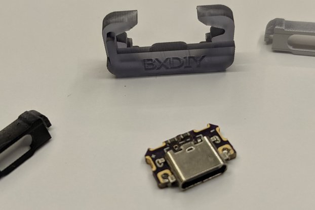
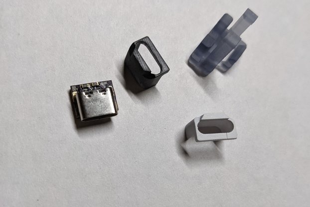
Place bezel over the USBC connector
Reassemble the backplate, make sure everything is working (charging, audio jack and speaker muting) before screwing it all back together. If the wires are routed poorly they can push against the battery cavity moving the battery away from its connector so watch out for this pitfall.
REQUIRED BUT NOT INCLUDED TOOLS:
(highly) RECOMMENDED BUT NOT INCLUDED TOOLS:
INCLUDED:
MOD DIFFICULTY: Tedious and fairly difficult definitely one of the harder ones.
FAQ: Can I charge while listening to headphones? -Yes Will the headphones mute the speakers? -Yes, if it doesn't you've wired something incorrectly. Can I listen to audio through the USBC port? -No, I tried using the recommended resistors to identify as an audio device but wasn't able to get it to work without removing a resistor and decided I preferred having a USBC port you can use both sides on. Is this mod hard? -Yes, I wouldn't recommend this to a newbie it requires patience and it is very easy to break wires during installation requiring you to start all over.
No country selected, please select your country to see shipping options.
No rates are available for shipping to .
Enter your email address if you'd like to be notified when GBASP DIY USBC charge port and audio jack kit can be shipped to you:
Thanks! We'll let you know when the seller adds shipping rates for your country.
| Shipping Rate | Tracked | Ships From | First Item | Additional Items |
|---|---|---|---|---|
|
:
|
Buy with confidence.
Our Tindie Guarantee protects your purchase from fraud. Learn More
$12.00
Free Shipping!
$12.00
Free Shipping!
$12.00
Free Shipping!
$12.00
Free Shipping!
$12.00
Free Shipping!

$12.00
Free Shipping!
$12.00
Free Shipping!
$12.00
Free Shipping!

$12.00
Free Shipping!

$12.00
Free Shipping!

$12.00
Free Shipping!

$12.00
Free Shipping!
By clicking Register, you confirm that you accept our Terms & Conditions
We recognize our top users by making them a Tindarian. Tindarians have access to secret & unreleased features.
We look for the most active & best members of the Tindie community, and invite them to join. There isn't a selection process or form to fill out. The only way to become a Tindarian is by being a nice & active member of the Tindie community!
