Sensor board w/ LTC4079 solar MPPT battery charger and NRF24l01+ radio socket
Designed by ceech in Slovenia
This product is no longer available for sale.
The seller may be offering an improved version or it may be hanging out on the beach, enjoying the retired life.
Sadly, we found out that this seller passed away in February 2020. Our condolences to his family and friends.
Charger IC has a complete constant current, constant voltage algorithm. It is a low quiescent current, high voltage linear charger for most battery chemistry types including Li-Ion/Polymer, Lead-Acid…
Read More…Charger IC has a complete constant current, constant voltage algorithm. It is a low quiescent current, high voltage linear charger for most battery chemistry types including Li-Ion/Polymer, Lead-Acid or NiMH battery stacks up to 60V. The maximum charge current is 100mA, set with a resistor. The battery charge voltage is set using a resistor divider. If no special instructions are made, the charge voltage is set to 4.2V.
Quiescent current while charging is 4µA
Ultralow battery drain when charged IBAT < 0.01µA
The LTC4079 charges the backup battery while greatly extends battery life. It lets you monitor voltages and charging current. The power source is a small, 5V - 20V solar cell. Connections:
analog input A7 on ATmega 328 is /CHRG signal from LTC4079
analog input A0 on ATmega328 is battery voltage
analog input A2 is solar cell voltage
analog input A6 is charge current
The 1Mohm trimmer potentiometer is used to determine the MPPT (multi point power tracking) point of the solar cell - to maximize its power. At shipping it is set to around 500kOhm, which sets the MPPT voltage of the solar cell to around 12V. The range is from 5V to 18V.
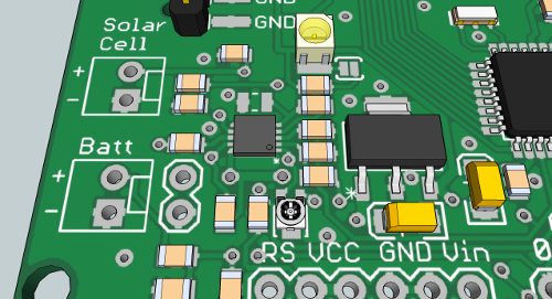
Setting the trimmer
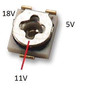 Voltmeters on both battery and solar cell connections are connected to analog inputs A0 and A2 on the ATmega328p. The voltage divider resistors on battery pins are equal, so the measured voltage is double the shown voltage. And the voltage divider resistors on solar cell pins are 47k over 10k. Take a look at the code example for measurement equation.
Other features on the board:
NRF24l01+ radio socket
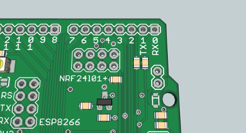 with CE and CSN pins connected to digital pins 7 and 8 ( you use RF24 radio(7, 8); in Arduino code). There is a 4.7uF capacitor connected across Vin and GND of the port NRF24
High efficiency buck-boost regulator
The board comes with a TPS63031, 3.3V DC-DC buck-boost converter. It has low power consumption of 30μA, typically, while delivering at least 500mA in boost mode.
I2C socket with SDA and SCL lines
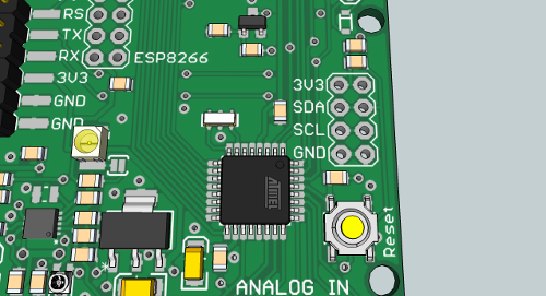 and 10k pull-up resistors for external I2C components, connected to A4 and A5
3amp 30V n-channel MOSFET for regulating external components such as solenoids. The gate is connected to D3 and the output is protected with a Schottky diode.
ESP8266 ESP01 socket
Low power (2mA) LED diodes are connected via solder jumpers. Jumpers need to be soldered in.
There are few such boards available and none with this kind of versatility. Fully Arduino compatible with Arduino PRO Mini 3.3V @ 8MHz bootlader.
This board is made for solar powered applications with batteries as backup. Identical - small - footprint as Arduino PRO. Only better. It is intended for sensor applications and can be used as an universal board for sensor node networks. Dimensions are 2 inch x 2.1 inch.
$24.90
Free Shipping!
$19.90
Free Shipping!
$19.90
Free Shipping!

$7.00
Free Shipping!
By clicking Register, you confirm that you accept our Terms & Conditions
We recognize our top users by making them a Tindarian. Tindarians have access to secret & unreleased features.
We look for the most active & best members of the Tindie community, and invite them to join. There isn't a selection process or form to fill out. The only way to become a Tindarian is by being a nice & active member of the Tindie community!
