This product is no longer available for sale.
The seller may be offering an improved version or it may be hanging out on the beach, enjoying the retired life.
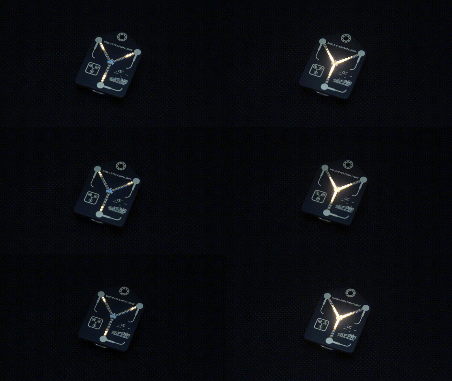
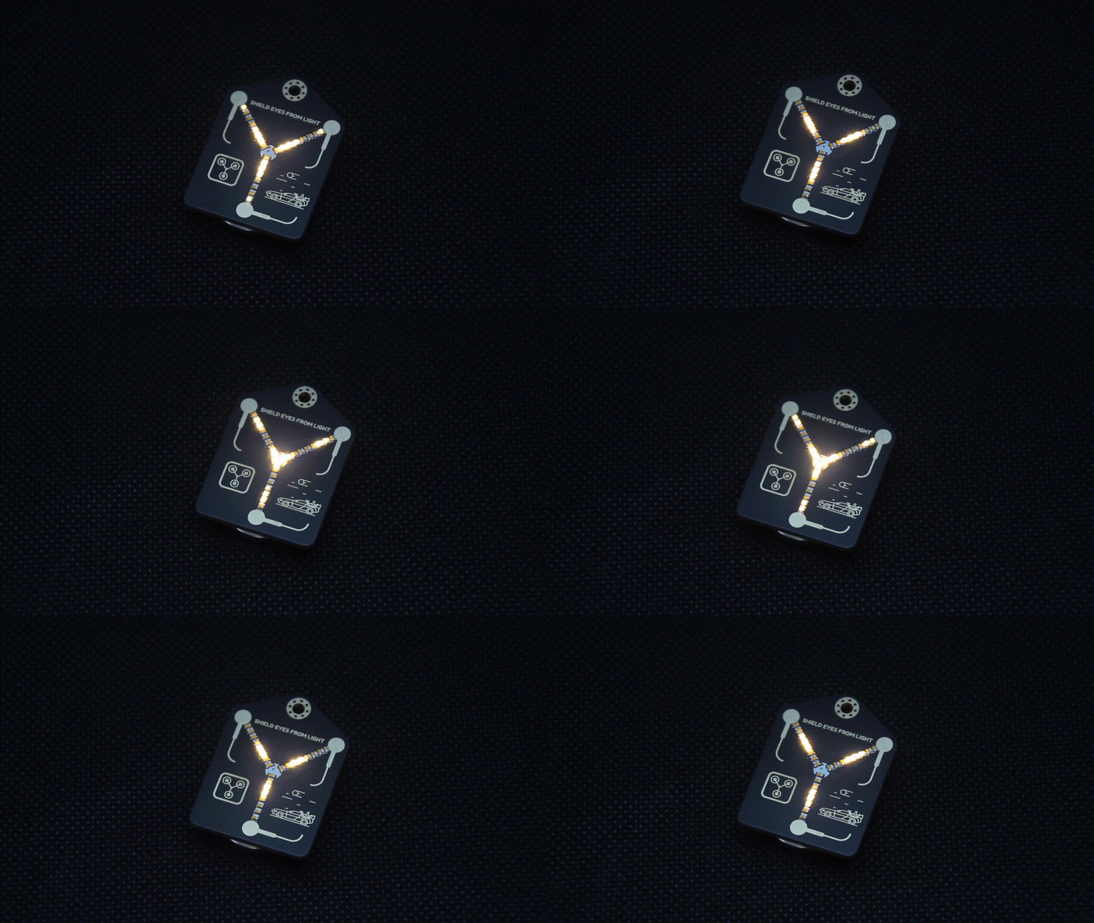
NEW REVISION IS AVAILABE HERE What is it? A tiny (35mm x 25mm) PCB badge featuring 24 LEDs that animate to create the “fluxxing” effect. It’s 100% decorative, it doesn’t actually let you travel throu…
Read More…A tiny (35mm x 25mm) PCB badge featuring 24 LEDs that animate to create the “fluxxing” effect. It’s 100% decorative, it doesn’t actually let you travel through time when worn around the neck.
It is controlled by a Microchip ATtiny816 microcontroller. Thankfully this board has a much lower power requirement than the silkscreen indicates on the back, and skips along, sipping power from the single CR2032/LIR2032 coin cell battery (instead of plutonium or a lightning strike), slipped into the rear mounted coin cell holder.


Thanks to Microchip’s latest ATtiny816 microcontroller now I can dim the LEDs with 8 individual PWM pins. Users can now change the animation type, animation speed, and LED brightness. There are 2 animation types (multi beam and single beam), 2 animation speeds (slow and fast), 4 LED brightness levels (100%, 75%, 50% and 25%). Power consumption is drastically lowered. At full brightness it draws 2.3mA and at 25% brightness it draws 1.1mA of current from the battery. Also front of the Flux Condenser is now much cleaner. Most of the via drill holes are now gone.
CR2032 (Non-Rechargeable) with average of 210mAh battery capacity.
LIR2032 (Rechargeable) with average of 40mAh battery capacity.
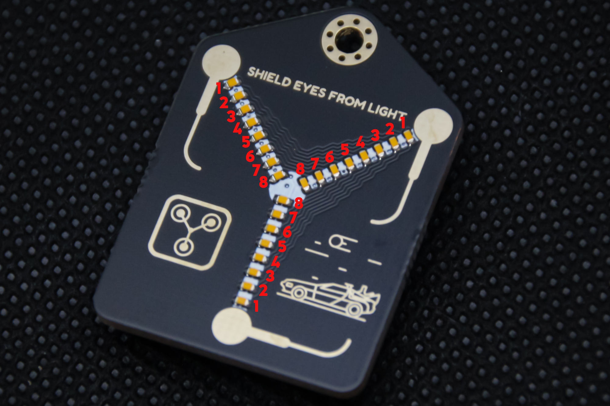
To set your desired animation, speed and LED brightness, you have to start flux condenser with configuration interface. In order to do that, you have to turn off your flux condenser. While holding the “Start” button on the back turn the flux condenser on. Now you should see configuration interface. Some of the LEDs should be on and some off according to your configuration. LEDs on each row of all columns, starting from outer to inner are paralleled.

Each LED number from photo shown above represents different setting.
To choose your preference just hold the start button. All the LEDs should turn off and after a second starting from LED1 each individual LED gets lit. Hold the start until the LED that represents your preferred setting is lit, then release the button. Now your new configuration is set. To see it in more detail check out the video at the end of the description.
I'm a huge fan of "Back to the Future" movies. I wanted to make a PCB version of the flux capacitor from the movies and give few to my best friends who introduced me to the "BTTF" trilogy. After I made them, I shared it on twitter and it got a lot of attraction from other people who wanted to get one for themselves. Then I decided to make more.
Batteries are not included due to shipping restrictions.
Product: (5.00)
Documentation: (4.50)
Shipping: (4.70)
Communication: (4.80)
Alex | June 13, 2022
Pablo | Jan. 12, 2022
Dirk | Oct. 14, 2021
Szabolcs | Oct. 11, 2021
Antonio | Oct. 8, 2021
Andrew | Oct. 5, 2021
Ingo | Oct. 5, 2021
James | Sept. 23, 2021
Tobias | Sept. 21, 2021
Michael | Sept. 15, 2021
By clicking Register, you confirm that you accept our Terms & Conditions
We recognize our top users by making them a Tindarian. Tindarians have access to secret & unreleased features.
We look for the most active & best members of the Tindie community, and invite them to join. There isn't a selection process or form to fill out. The only way to become a Tindarian is by being a nice & active member of the Tindie community!
