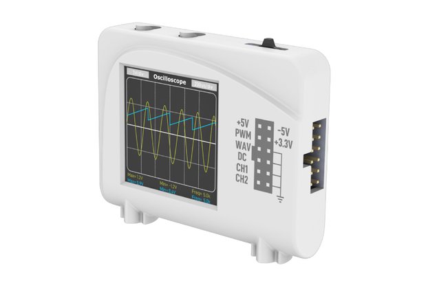
2-Channel, 500kS/s, 150kHz oscilloscope with FFT, X-Y mode, cursors and signal generator
Designed by Yezzmod Audio in Australia
This product is no longer available for sale.
The seller may be offering an improved version or it may be hanging out on the beach, enjoying the retired life.
The DSO500K-U is a 2-Channel 500kS/s oscilloscope with a maximum analog bandwidth of 150kHz and is ideal for measuring low voltage signals. Our Scoppy Android app is used to control the scope and dis…
Read More…The DSO500K-U is a 2-Channel 500kS/s oscilloscope with a maximum analog bandwidth of 150kHz and is ideal for measuring low voltage signals. Our Scoppy Android app is used to control the scope and display the waveform data. The oscilloscope connects to your Android device via USB. If you would prefer an oscilloscope that also allows wireless connectivity check out our DSO-500K Oscilloscope.
> You might also be able to run the Scoppy app in Windows using Android-x86 on a VM. However we don't provide official support for this. See this awesome instructional video by picoLabo (Japanese with English captions).
Despite its low price, the DSO500K-U includes standard oscilloscope functionality (vertical, horizontal, triggering) and well as features not available on most other oscilloscopes in this price range such as FFT, X-Y mode, cursors and roll mode - not to mention that 2nd channel.
The DSO500K-U has been designed to be as affordable as possible while not compromising on quality. We use genuine Microchip op-amps and Nexperia analog switches in the buffer and pre-amplifier sections of the oscilloscope. Data aquisition and triggering are handled by the onboard RP2040 microcontroller.
While there are other inexpensive oscilloscopes on the market, most have simple but clunky user interfaces and generally small and low quality displays (not to mention exaggerated specifications). We thought we could do better.
By using using an Android device to control the oscilloscope and display the waveforms we have been able to create a very affordable 2 channel oscilloscope that has an intuitive, easy to use and fully featured user interface (see the reviews on the Play Store). The waveforms and controls are displayed on the large, high definition screen found on your Android device. Pair the DSO500K-U with a 10" tablet and you have an oscilloscope with a display larger than many benchtop 'scopes (though we don't claim the DSO500K-U is a substitute for a benchtop oscilloscope!).
Whether STEM student, educator, electronics hobbyist, maker or even field technician, the DSO500K-U is for anyone who wants a super cheap 2-channel oscilloscope that has a maximum bandwidth of 150kHz and maximum input voltage range of ±15V with 10X probes (or ±6V with 1X probes). It also has the advantage of portability and is completely isolated from the mains supply.
The DSO500K-U is designed for measuring signals below 150kHz and ±15V and so can be used for applications such as 555 timer circuits, op-amp circuits, diode clipping and clamping circuits, automotive, audio, transistor circuits and some filters - in fact just about any circuit where voltage changes over time and where the signals are within the voltage and frequency limits of the DSO500K-U.
The limited bandwidth and input voltage range means it will never replace a real benchtop oscilloscope. But for makers, those new to the hobby or STEM students it can be used as a learning tool and give a feel for what a more expensive oscilloscope can do.
The DSO500K-U supports AUTO and NORMAL trigger modes and RISING EDGE and FALLING EDGE trigger types. The trigger level is set either by dragging the trigger indicator, tapping the trigger level buttons or tapping the trigger badge at the bottom of the screen. Long-pressing the LEVEL button will set the trigger level to the center of the displayed waveform.
Horizontal and vertical cursors are available in both YT (ie. normal oscilloscope) and FFT modes. In YT mode, the horizontal (X) cursor measurements include position, period and frequency. Vertical (Y) cursor measurements include the voltage and the delta between the two cursors.
Standard X-Y mode as found on most oscilloscopes. Also includes a LINES option to join all samples points with lines instead of displaying individual dots. This can make the output look much nicer for some signals.
The X-Y mode view can be displayed simultaneously with the YT waveforms.
Displays the waveform data as it is captured instead of waiting for the complete waveform record. Roll mode is used when the sample rate drops below 1kS/s.
Tapping the ROLL button will enter roll mode and set the Time/Div to 1s/div. Tapping it again will leave roll mode and set the Time/Div back to its previous value.
Pressing the SINGLE button will capture a single waveform record of up to 100k samples. Can be used with either AUTO triggering (to capture the waveform immediately) or NORMAL triggering (to capture the waveform after a trigger event occurs).
Headers can be soldered to the board to access the Logic Analyzer inputs. The logic analyzer sample rate is 25MS/s and the maximum voltage is 3.3V.
Protocol decoding is not available but the waveform record can be saved and imported into other software (eg. sigrok/pulseview).
Removing the jumpers from the DC coupling pins will enable AC coupling.
On screen measurements include Vmin, Vmax, Vpp, Frequency, Time (Period) and Duty Cycle for each channel. Tapping the measurements will open the configuration screen. The configuration screen can also be accessed via the channel badges.
Measurements can be displayed for a single waveform (snapshot). These snapshot measurements can encompass the entire sample record or just those samples displayed on the screen. The measurements available include Vmin, Vmax, Vpp, Vmean, Vdc-rms, Vac-rms, Frequency, Period and Duty Cycle. The snapshot measurements can be displayed by long-pressing the on-screen measurements or via the channel badges.
The signal generator can produce square waves of between 10Hz and 200kHz or a PWM encoded sine wave of 1kHz. The PWM encoded sine wave can be converted to an analog sine wave using a low pass filter.
Detailed documentation is available for the app and hardware. While the intuitive user interface of the Scoppy Android app means it can easily be used without consulting the documentation, you might - for example - be interested in discovering the five different ways of changing the horizontal timebase. We encourage you to check out the independent reviews of the app on the Play Store.
The DSO500K-U is powered by a Raspberry Pi RP2040 MCU and so can be used as a normal RP2040 development board if you decide you no longer want to use it as an oscilloscope.
To keep the price as low as possible, the board does not have BNC connectors on the inputs. Instead the board has 0.1" (2.54mm) headers and inexpensive Dupont wires can be used as probes.
However for those of you wanting to use real oscilloscope probes, BNC connectors can be purchased separately and easily soldered to the board.
| Quantity | Price |
|---|---|
| 1 | $19.99 |
| 2-4 | $17.99 |
| 5-9 | $16.99 |
| 10-19 | $15.99 |
| 20-49 | $14.99 |
| 50+ | $13.99 |

$40.50
Free Shipping!

$26.00
Free Shipping!

$300.00
Free Shipping!

$99.00
Free Shipping!
By clicking Register, you confirm that you accept our Terms & Conditions
We recognize our top users by making them a Tindarian. Tindarians have access to secret & unreleased features.
We look for the most active & best members of the Tindie community, and invite them to join. There isn't a selection process or form to fill out. The only way to become a Tindarian is by being a nice & active member of the Tindie community!
