Adjustable Electronic Load, capable of 180Watts to 240Watts Power Dissipation
Designed by FiveFish Audio in United States of AmericaThis seller is taking a break. Sign up below to get an email when they're back!
No shipping info available.
Set destination country to see options
Shipping to starts at
Free shipping is available to !
Ships from
This item does not ship to .
More Info
Sign up and we'll send a reminder when the seller returns!
NOTE: You are purchasing a PCB only. Some assembly required. Additional parts required. Photo shown is the finished product after successful assembly following our instructions guide. I needed an ele…
Read More…NOTE: You are purchasing a PCB only. Some assembly required. Additional parts required. Photo shown is the finished product after successful assembly following our instructions guide.
I needed an electronic load to test my power supplies, but commercial units asks for too much money. And the cheap ones available, are too wimpy to deal with the voltages and current I usually work with, or they're more designed to be connected to low power batteries. Bottomline, I need something more substantial and thus this project was born.
This is an adjustable constant current Electronic Load PCB, when assembled completely, can be used for testing of amplifier power supplies, hi-fi power supplies, DIY project power supplies, DC-DC switching converters or batteries.
Just dial the knob on how much current draw you'd like (from a few milliamps to several amps), and the electronic load will do it's job of dissipating all that energy/power (Volts x Current) from your PSU under test. A 12VDC power supply (can be supplied by a wall wart) is all that is required by this Electronic Load.
Two heavy-duty CPU heatsinks with integrated cooling fans are used to keep the power MOSFETs (TO-247 package) cool, allowing you to dissipate anywhere from a few watts to couple hundred watts of power in a very small package. Intel put a lot of engineering effort into their heatsinks for use with their hot CPUs, so it's to our benefit we use them! You can find these CPU heatsinks on eBay for less than $10! :) NOTE: You will need to tap the solid copper core of the heatsink with a 4-40 threaded hole. This gives you the benefit of bolting the MOSFETs directly to the copper core, providing maximum & efficient heat transfer. (TO-247 insulators are optional, but just note the heatsink will be at V+ potential if you don't use Mica or SilPad insulators.)
A BNC connector is also included so you can connect this Electronic Load easily to your oscilloscope (using BNC-to-BNC cable) -- to monitor the power supply output at varying amounts of current draw/load. This is especially useful when testing DC-DC switching buck/boost/inverting converters so you can see how different amount of current draw affect the DC output waveform on the scope.
Features: - Constant Current, Adjustable Current Load - Designed for use with two heavy-duty heatsinks with integrated cooling fans - Two Power MOSFETs operating in parallel to achieve SOA (Safe Operating Area) - 10-turn multi-turn potentiometer for fine-control of the current draw - Simple 12VDC operation, wall wart or equivalent - Real-world tested at 60V @ 3Amps (180Watts), 30V @ 6Amps (180Watts), 120V @ 2Amps (240Watts) for 30 minutes duration! - Heavy-duty, screw-on terminals for attaching DUT (Device Under Test) Power Supply - Read-out of actual current draw/load via simple voltmeter, 1mV reading = 1mA current draw
Note: This is a PCB only. Schematic, and Parts List can be found on our website at http://fivefishaudio.com/diy/eload/
Photos below is representative of what an assembled unit will look like.
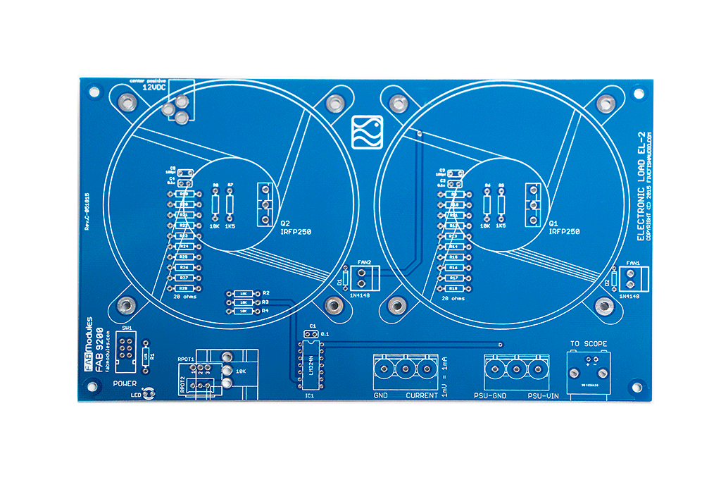
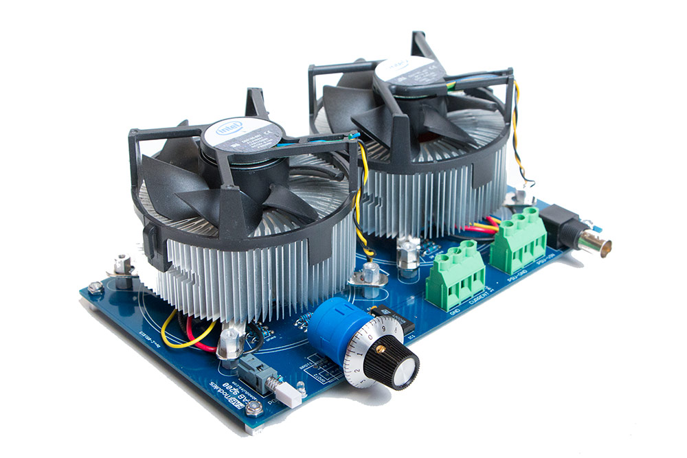
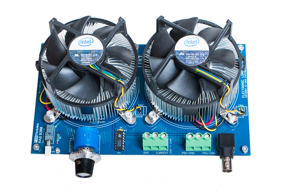
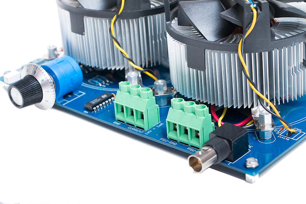
Dissipating 180Watts (60V @ 3.0Amps)
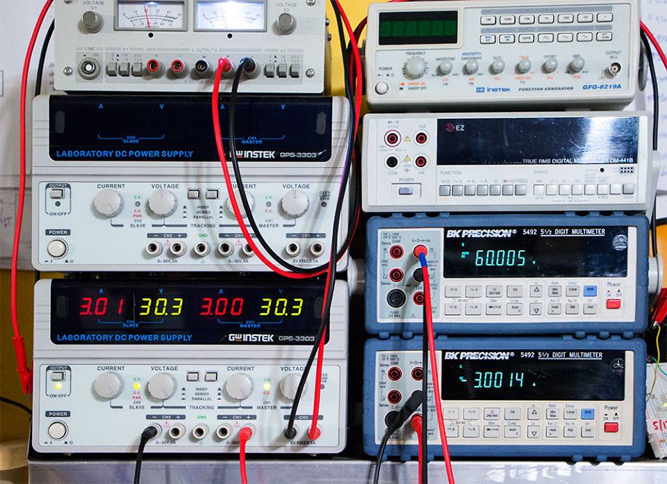
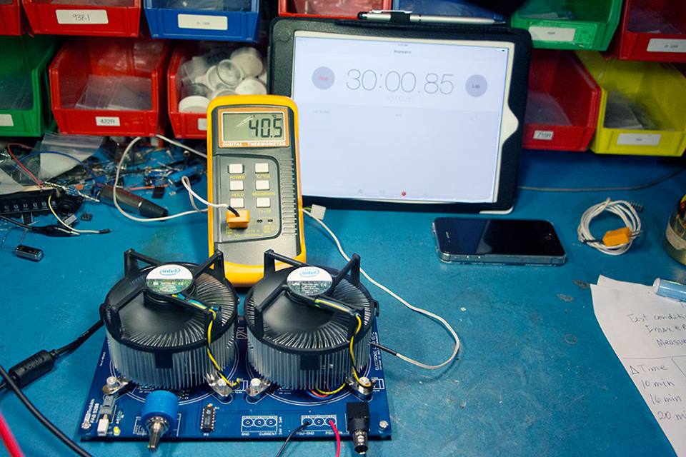
With temperature probe connected to CPU heatsink, temperature reading is shown after 30 minutes of continuous operation.
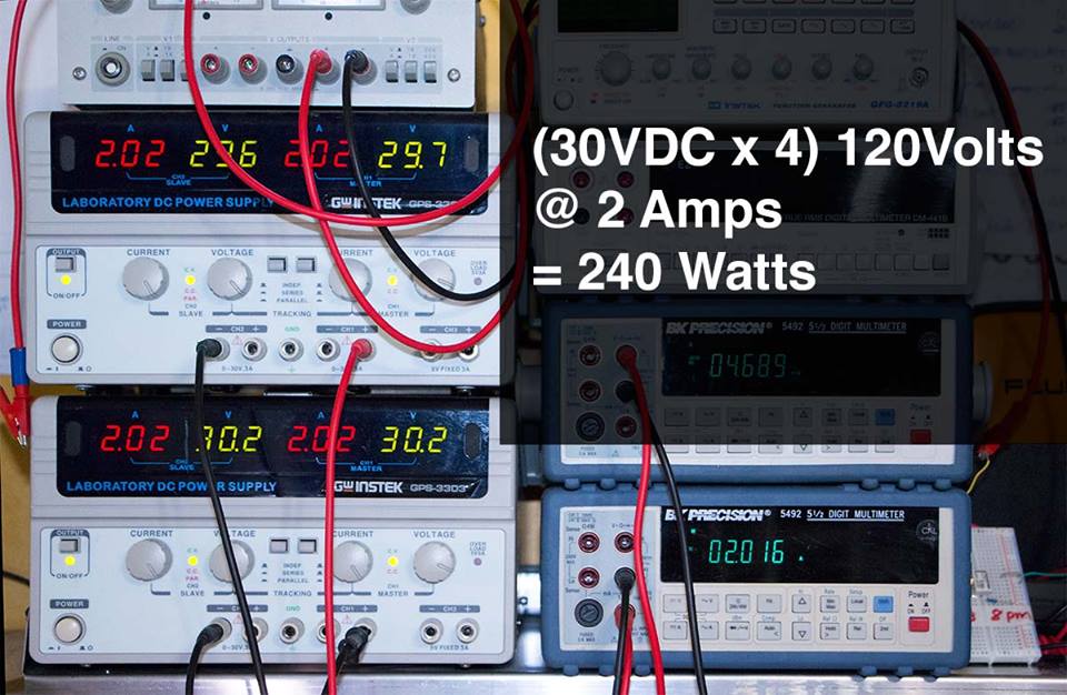
Tested at 120VDC @ 2Amps (240 Watts)! It's probably possible to go even higher, but you will need more fans and bigger heatsinks to blow heat away faster. Now, you're battling rising temperature rather than limitation of the Power MOSFETs.
ERRATA/PERFORMANCE IMPROVEMENTS:
C2, C3, C4, C5 : [DO NOT POPULATE]
Cfix : Add 0.47uf 50V Electrolytic in parallel with R6 & R8.
30V/3A scope display. Very stable. No oscillation. Very low ripple. 3mV RMS.
Watch this YouTube video to see the Electronic Load in action. https://www.youtube.com/watch?v=Nw80aH2WYxE
See website for schematic and parts list. http://www.fivefishaudio.com/diy/eload/
No country selected, please select your country to see shipping options.
No rates are available for shipping to .
Enter your email address if you'd like to be notified when 180W-240Watt Electronic Load PCB can be shipped to you:
Thanks! We'll let you know when the seller adds shipping rates for your country.
| Shipping Rate | Tracked | Ships From | First Item | Additional Items |
|---|---|---|---|---|
|
:
|
Product: (5.00)
Documentation: (4.50)
Shipping: (5.00)
Communication: (4.50)
Andrew | Feb. 20, 2020
Samuel | March 5, 2016
No shipping info available.
Set destination country to see options
Shipping to starts at
Free shipping is available to !
Ships from
This item does not ship to .
More Info
Sign up and we'll send a reminder when the seller returns!
Brentwood, TN, United States of America
Ships from United States of America.
2 Reviews | 82 Orders
$29.00
Free Shipping!
$13.00
Free Shipping!
$129.00
Free Shipping!
$139.00
Free Shipping!
$18.00
Free Shipping!
$33.24 $34.99
Free Shipping!
$33.24 $34.99
Free Shipping!
$6.99
Free Shipping!

$42.00
Free Shipping!
By clicking Register, you confirm that you accept our Terms & Conditions
We recognize our top users by making them a Tindarian. Tindarians have access to secret & unreleased features.
We look for the most active & best members of the Tindie community, and invite them to join. There isn't a selection process or form to fill out. The only way to become a Tindarian is by being a nice & active member of the Tindie community!
