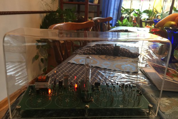
An analog style oscilloscope clock kit, OSC4.9, where the display is generated from a sine wave oscillator.
Designed by Oscilloscope clocks in United States of America
Buy with confidence.
Our Tindie Guarantee protects your purchase from fraud. Learn More
This is a store featuring my homemade electronic novelty clocks, made using obsolete electronic tubes, and my kits designed for diy for these clocks.
Https://www.youtube.com/shorts/8FiZdIDpQZY OSC4.9 is a purely analog version, where the signal from a sine wave oscillator is controlled by a microcontroller to form the circles, arcs and lines that …
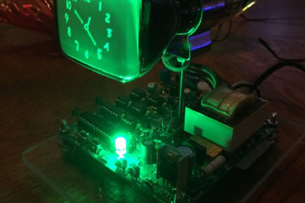
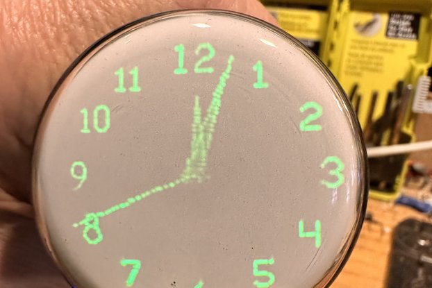
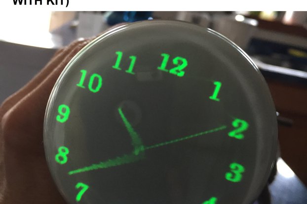
Read More…https://www.youtube.com/shorts/8FiZdIDpQZY OSC4.9 is a purely analog version, where the signal from a sine wave oscillator is controlled by a microcontroller to form the circles, arcs and lines that create the display. Assembly required. Please note: a CRT is not included. Image is for demonstration only. The kit is a professionally made pc board and the components to populate it, including the ICs and the preprogrammed microcontrollers written with my firmware, and the power transformer. The photos of the CRT are for demonstration only, please note: A CRT is not included, nor is an enclosure, only the parts listed. So the kit provides the materials to build the driver board and the builder will source their own CRT to connect it to, and install it in their enclosure. The CRT clock in the enclosure is shown only as an example; the CRT and the enclosure are not included in the kit. Also, please note: This is an unassembled kit, the assembled board is shown only for reference. There is also a port in back for gps module or wifi module option, the input for automatic time / date set. It uses a simple low voltage dual secondary transformer and a line fed voltage multiplier for the HV. I supply the instructions for assembly and a parts list with the board and components. You can download the Documentation, Datasheet and BOM from this page. The complete list of components included in the kit are:
Parts list:
Capacitors:
2 - 4.7uF, 450V(electrolytic)
9 - .1uF (104)(ceramic)
1 - 1,000uF,16 - 25V(electrolytic)
1 - 100uF, 6.3 - 25V(electrolytic)
2 - .01uF (103)(tantalum)
4 - .001uF (102)(tantalum)
1- .0001uF (101)(tantalum)
1 - .047uF (473)(tantalum)
Potentiometers:
1 - 50K or 47K, .25W top adjust (503 or 473)
2 -1M, .25W top adjust (105)
2 - 50K, .12W side adjust
2 – 50K, .12W top adjust
1 – 100K, .12W top adjust (104)
1 – 5K or 4.7K .12W top adjust (502 or 472)
1 – 300K .12W top adjust (304)
1 – 10K .12W top adjust (103)
1 – 1K .12W top adjust (102)
Diodes:
2 - 1N4007
2 - 1N4001
Miscellaneous:
3 - push buttons
1 - DPDT Relay 7 – 10 V coil, non-latching
1 - Rectifier Bridge 25V #512-2KBP01M
1 - 5V regulator 7805
1 - solder-in fuse
1 - led
1 - neon lamp
1- four pin header & jumper
1 - Transformer-120V/240V prim., 7-9 V sec
10 - Wires / 2 hookup wires
IC Sockets:
1 - 28 pin
1 - 14 pin
7 - 8 pin
Transistors:
5 - MPSA44(NPN) (alternate - 2N6517 NPN)
1 - MPSA92(PNP)
4 - 2N3904(NPN)
Resistors:(1/4 Watt, unless otherwise noted)
2 – 180K (brown grey yellow)
1 - 47K (yellow purple orange)
12- 10K (brown black orange)
10 - 4.7K (yellow purple red)
8 - 2.2K (red red red)
2 - 330K (orange orange yellow)
1 – 3.3K (orange orange red)
2 - 220K (red red yellow)
3 - 1K (brown black red)
1 - 10M (brown black blue)
1 - 100K (brown black yellow)
2 - 1.6K (brown blue red)
1 - 470K, ½ W (yellow purple yellow)
1 - 5 ohm or 4.7 ohm, 1W (yellow purple gold)
1 - 10 ohm, 3W (brown black black)
Chips:
1 - PIC18f26k20
1 - 4066
2 – 4132 (104)
2 – DS1804 (CAT5113)
2 – 3307 (op amps)
Optional GPS/WiFi Module:
5 – pin edge connector
5 – pin header
WifiModule kit or GPS module
antenna (gps)
Instruction set for scope clock:
It can be set for either 120VAC or 240VAC, please see the small four pin header marked 120> <240 and set the jumper on the appropriate two pins.
Instruction set for analog scope clock OSC4.9:
When plugged in, the blue led should light immediately, and in five seconds, there should be a small "click" of the relay engaging. The neon light in the back should glow orange. After several minutes, the filament should warm sufficiently and the screen should display "1", (number one). This means 60HZ was detected and set accordingly. If a zero appears instead, then 50HZ was erroneously detected (unless your country uses 50HZ mains of course). Unplug, wait until the blue led goes off, and then plug back in.
If the screen only displays a dot, or if the display is not well formed, you may need to adjust OSC SHAPE (P10). Using a small screwdriver, turn the dial slowly clockwise until a circle appears onscreen. If the screen does not display anything after five minutes, unplug and wait one minute then plug in again.
The time set buttons are a pair situated close together, one is slow set, and the other fast set. To set time without programming any preset on/off times, just press the slow set button (on the left) once and the clock display should appear, then use the two buttons on the front to set time.
To set for Wifi/GPS:
When the “1” (or “0” for 50HZ) initially appears, press “toggle” once to select your time zone.
Cycle through the time zones by pressing “fast set” to increment to the correct time zone (i.e, for EST = “01”) (Once selected, it will be stored in EEPROM, no need to select it again)
When the correct time zone appears, press “slow set” once to return to set up.
Press fast set once to enter date select screen. If choosing date display, press toggle once to select.
Press fast set again to enter time keeping mode.
The screen should display correct time. GPS modules may take several minutes to acquire a satellite lock.
To refresh the data, press slow set & toggle simultaneously.
To manually turn the display on/off, press the “toggle” button on the right side (separate from the two set buttons).
To program the preset on/off times: First press slow set to enter normal timekeeping mode, then press the fast set
& slow set buttons at same time and the screen should display 12:00:00. The seconds will not count in this mode.
Press & hold the fast set button to increment the hours. Each time that button is pressed, the hours should increment once.
When the desired hour is shown for ON time (AM only), press the toggle button to advance to the next screen and the display should change again to 12:00:00. Follow the same procedure, and after the OFF time is selected, either press slow set to enter normal timekeeping (fast set / slow set) mode or, to set the second set of preset on / off times, press toggle and follow the same procedure, except this time you will be selecting first a PM on time and then an AM off time. Please refer to the youtube link for illustration: Note: The clock will display 12:00 AM to start, so if the present time is after noon, you will need to advance the time past 12:00 in order to reach the PM hours, else the preset on/off times may be reversed. I.E.: if the present time is 8:00 PM, you need to advance PAST 8:00 once, and then stop at 8:00.
To change the display mode, press fast set & toggle button together and the display mode will change to a “0” (zero).
Press fast set to cycle through 0, 1 & 2. 0 is the alternating display (default), select 1 for digital only & 2 for analog only.
Press slow set when you have made your selection to return to normal timekeeping mode. This will start again at 12:00 AM.
To set DST (daylight savings):
Press fast set & toggle to enter display mode, then press toggle to enter DST mode.
Press fast set to change between 0 & 1.
0 = DST off (Spring to Fall)
1 = DST on (Fall to Spring)
Press slow set to exit & return to run mode.
Time Zones :
1 = EST
2 = CST
3 = MST
4 = PST
5 = AKST
6 = HAST
7 = BST
8 = CEST
9 = MSK
10 = PHT
11 = ACST
12 = GST
13 = AEST
No country selected, please select your country to see shipping options.
No rates are available for shipping to .
Enter your email address if you'd like to be notified when OSC4.9 analog style Oscilloscope Clock Kit for CRT can be shipped to you:
Thanks! We'll let you know when the seller adds shipping rates for your country.
| Shipping Rate | Tracked | Ships From | First Item | Additional Items |
|---|---|---|---|---|
|
:
|
Buy with confidence.
Our Tindie Guarantee protects your purchase from fraud. Learn More
Finksburg, MD, United States of America
Ships from United States of America.
4 Reviews | 110 Orders
$395.00
Free Shipping!

$325.00
Free Shipping!
$325.00
Free Shipping!

$325.00
Free Shipping!
$105.00
Free Shipping!
$130.00
Free Shipping!

$265.00
Free Shipping!
$175.00
Free Shipping!

$175.00
Free Shipping!
$7.69 $10.99
Free Shipping!
$200.00
Free Shipping!
$2950.00
Free Shipping!
By clicking Register, you confirm that you accept our Terms & Conditions
We recognize our top users by making them a Tindarian. Tindarians have access to secret & unreleased features.
We look for the most active & best members of the Tindie community, and invite them to join. There isn't a selection process or form to fill out. The only way to become a Tindarian is by being a nice & active member of the Tindie community!
