The robot chassis control board uses a PIC microcontroller to actuate relays connected to a robot chassis and detect input from sensors
Designed by Oscilloscope clocks in United States of America
Buy with confidence.
Our Tindie Guarantee protects your purchase from fraud. Learn More
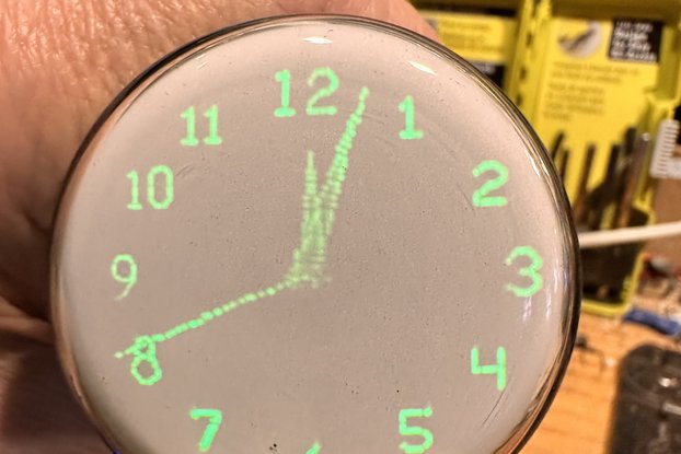
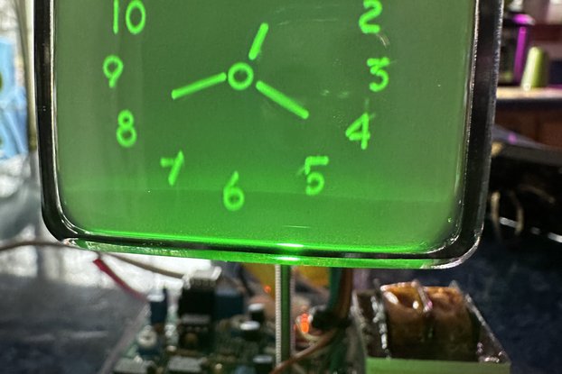
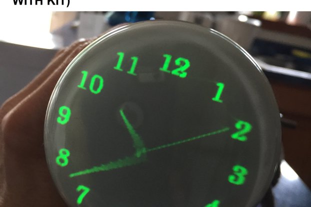
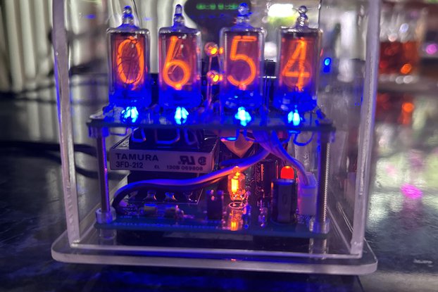
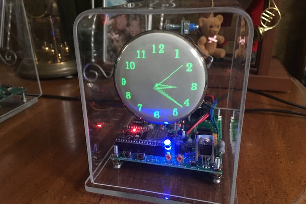
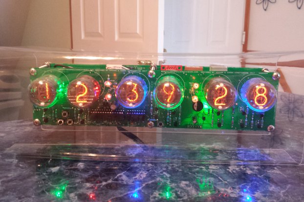
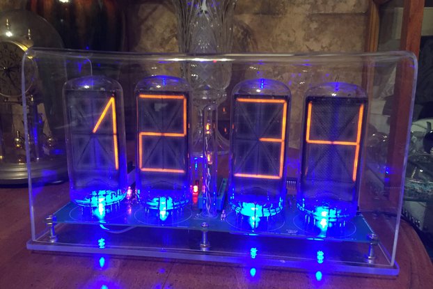
This is a store featuring my homemade electronic novelty clocks, made using obsolete electronic tubes, and my kits designed for diy for these clocks.
The Robot Chassis Control Board is a simple design I made for easy experimenting using different chassis. This homemade prototype pc board has four relays controlled by a 16f628a PIC microcontroller.…
Read More…The Robot Chassis Control Board is a simple design I made for easy experimenting using different chassis. This homemade prototype pc board has four relays controlled by a 16f628a PIC microcontroller. It also has sensor input from three IR emitter / detector pairs so the proximity to an obstacle can be detected, as well as an input from an electret microphone to detect & respond to sharp sounds like a hand clap. The 16f628a also controls an RGB led for visual feedback and a piezo buzzer for generating basic sounds.
There is a header pin connector on the board for ICSP programming, and also a header pin connector for the four I/O pins not used on the board so these can be accessed for extending the design to include more sensors and/or controls.
Here you can see a youtube video of the original (point to point wired) prototype on a small chassis (chassis is not included):
I am supplying the source code which is written in assembly and can be edited using MPLAB IDE, a free download from Microchip. The code will be commented to explain what's happening in each section. All one needs to edit the code is an IDE like MPLAB & a programmer to flash the microcontroller. Of course, programs could be written to the microcontroller using any system suited to PICs. The two chips on the board are the microcontroller and the op amp, and they are both socketed. As in all my board designs, no SMT components are used, everything is standard size so it can be built easily.
The board is powered by a nine volt battery, and the relays connect the motors (or other device) to a separate power supply. This allows the board to be used with different chassis powered independently. So for instance, the board could control a large chassis with motors powered by 12 volt batteries and this would work fine.
This video is of the assembled board connected to a small chassis (chassis is not included in the kit).
No country selected, please select your country to see shipping options.
No rates are available for shipping to .
Enter your email address if you'd like to be notified when Programmable Robot Chassis Control Board Kit can be shipped to you:
Thanks! We'll let you know when the seller adds shipping rates for your country.
| Shipping Rate | Tracked | Ships From | First Item | Additional Items |
|---|---|---|---|---|
|
:
|
Buy with confidence.
Our Tindie Guarantee protects your purchase from fraud. Learn More
Finksburg, MD, United States of America
Ships from United States of America.
4 Reviews | 109 Orders
$105.00
Free Shipping!
$100.00
Free Shipping!
$130.00
Free Shipping!

$265.00
Free Shipping!
$175.00
Free Shipping!
$300.00
Free Shipping!
$200.00
Free Shipping!
$2950.00
Free Shipping!
By clicking Register, you confirm that you accept our Terms & Conditions
We recognize our top users by making them a Tindarian. Tindarians have access to secret & unreleased features.
We look for the most active & best members of the Tindie community, and invite them to join. There isn't a selection process or form to fill out. The only way to become a Tindarian is by being a nice & active member of the Tindie community!
