Raspberry Pi Pico (RP2040) based board with integrated RTC and SD Card reader.
Designed by Invector Labs in SwedenThis seller is taking a break. Sign up below to get an email when they're back!
No shipping info available.
Set destination country to see options
Shipping to starts at
Free shipping is available to !
Ships from
This item does not ship to .
More Info
Sign up and we'll send a reminder when the seller returns!
The Challenger RP2040 SD/RTC is a small embedded computer equipped with a micro SD card reader as well as a Real Time Clock (RTC), in the popular Adafruit Feather form factor. It is based on an RP204…
Read More…The Challenger RP2040 SD/RTC is a small embedded computer equipped with a micro SD card reader as well as a Real Time Clock (RTC), in the popular Adafruit Feather form factor. It is based on an RP2040 micro controller chip from the Raspberry Pi foundation which is a dual core Cortex M0 that can run on a clock up to 133MHz.
We paired the RP2040 micro controller with a 8MByte high speed flash capable of supplying data up to the max speed. The flash memory can be used both to store instructions for the micro controller as well as data in a file system and having a file system available makes it easy to store data in a structured and easy to program approach.
The embedded micro SD card reader can be used to store huge amounts of data, great for those logging applications where you need to catch all that important sensor data.
Coupled with that we also included a real time clock (RTC) circuit on board that will allow you to capture the exact time that data came in. Connect a RTC-backup battery and you never have to worry about time any more =)
The board is based on a popular form factor called “Feather” which is created and maintained by an American company called Adafruit. The entire specification for the Feather format is available here. The size of the PCB for the module is 50.80mm x 22.86mm but the entire module is a little bit bigger as the Type C USB connector protrudes about 1 mm outside the board.
The micro SD card reader is located on the opposite end of the board from the USB-C connector. The reader accepts standard micro SD cards and so far we haven’t found a card that doesn’t work with our board. The card is inserted into the connector parallel to the board. It should be inserted firmly (but not to hard) to make sure that the detect switch is closed.
The board has an on board real time clock connected to the common I2C bus. The device used is microchip MCP79410 that can provide very high accuracy, with internal trimming registers, if required.
On each of the longer sides of the PCB there are holes intended for soldering pin header connectors. If you don’t want to use connectors for some reason you can also solder a wire directly into the hole, making a permanent connection to your external device. If you go this way please make sure that the wires are fixed in place, otherwise vibrations can cause the wire to brake at the soldering point.
On each side of the USB connector there is a small indicator LED placed. The LED which is marked CHG is the charge control indicator. This red LED will shine whenever the connected battery is being charged, and when the battery is fully charged the LED will turn off again. If you haven’t connected a battery to the board this LED will not come on at all.
On the other side of the USB connector there is a user programmable green LED. This LED is connected to pin D18 and can easily be controlled by the user program.
The on board micro controller (RP2040) have a number of communication channels that have been routed out to the side (header connector) connectors.
The pin chart below shows the placement of all pins and their respective functions. When working in an Arduino environment (or Platform IO) use the blue pins when writing your code and when working with CircuitPython use the orange marked pin assignments.
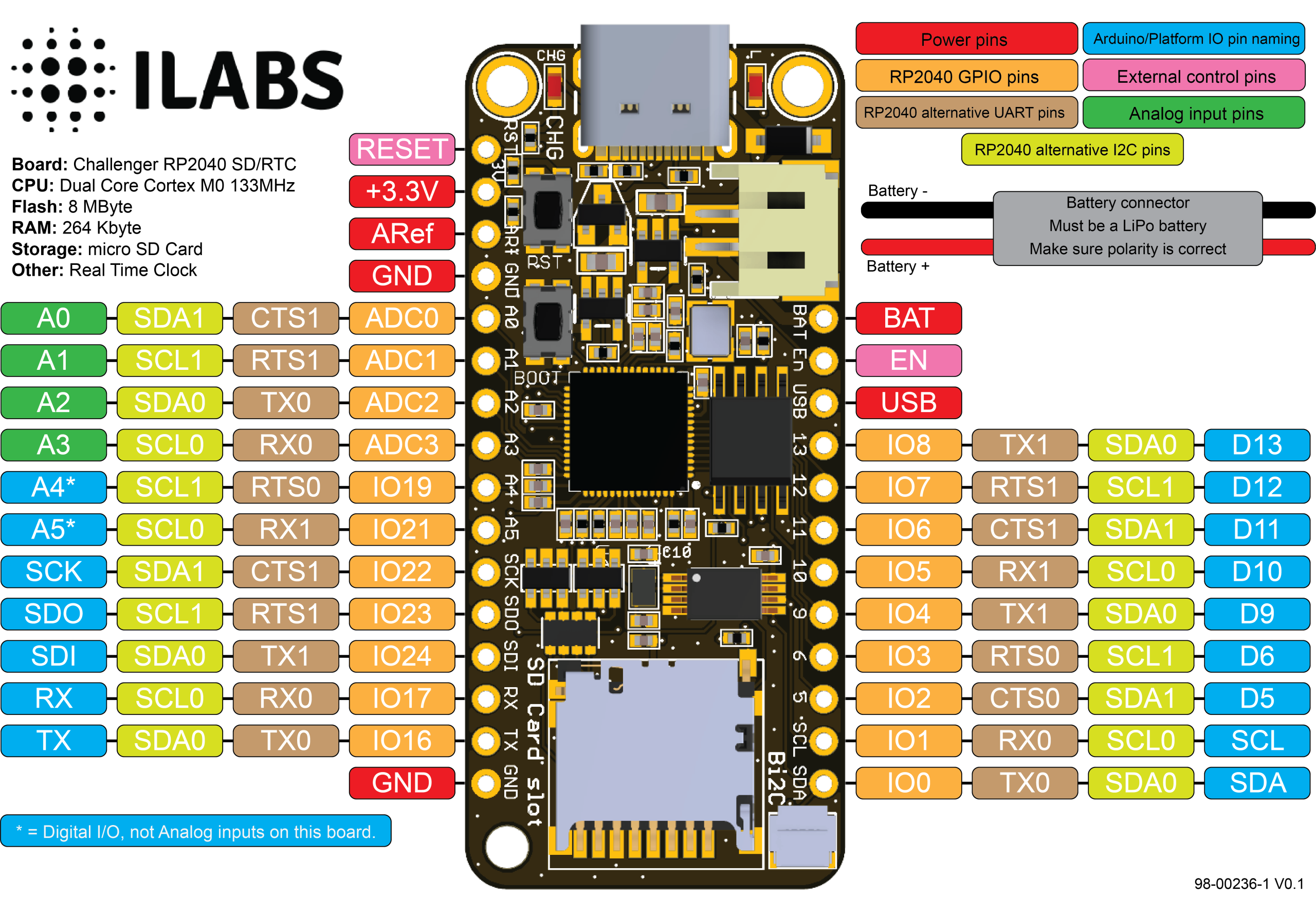
The board can be powered from multiple sources. The most obvious way to run the board is by plugging it in to a USB cable and attach it to your computer. In this mode you can write software and test the board with all its functionality.
There is also a third way to supply the board. This way is more invasive and will disable the onboard 3.3V power regulator.
You will have to pull the EN header pin low and then supply your own 3.3V voltage on the 3.3V header pin. Please note that when disabling the onboard power regulator you will have to supply the 3.3V also when running the system on battery power.
As mentioned earlier the board can be powered from a LiPo battery. The battery can be connected using a standard 2.0mm JST connector through the battery connector on the right side of the board or ff the battery is an integral part of the system that you are designing it is possible to connect the battery through the BAT pin instead.
Switching between the battery voltage and the applied USB voltage or external 5V is done seamlessly by the on board circuitry.
Charging of the battery is done by either connecting a USB cable or by connecting a 5V power source to the header pin marked USB on the board. If you do this make sure you connect your voltage through a 1A schottky diode to avoid any excessive current draw in the system when the two levels are slightly different.
Please note that providing external charger circuitry could destroy the internal charger on the Challenger board.
Connection between MCU and the SD card.
The processor connects to the SD card via the SPI1 communication channel.
In addition to the described signals a card detect signal is also connected to the connector. When this signal is logically low a card has been inserted and when it is high the card has been removed.
In order to be able to accurately time stamp logged entries we have included a MCP79410 RTC on board. The MCP79410 Real-Time Clock/Calendar tracks time using internal counters for hours, minutes, seconds, days, months, years, and day of week. Alarms can be configured on all counters up to and including months. For usage and configuration, the MCP79410 supports I2C communications up to 400 kHz.
The RTC also contains 64 bytes of battery backed up SRAM as well as 128 bytes of EEPROM that is easily accessed over the I2C bus.
An external 3V battery can also be connected to the RTC via 2 solder points on the backside of the board. Here you can solder in an external 3V lithium battery och battery holder that is used to power the RTC while there is no power to the board. This is useful for systems where it can be tricky to set the time when the power has been lost.
No country selected, please select your country to see shipping options.
No rates are available for shipping to .
Enter your email address if you'd like to be notified when Challenger RP2040 SD/RTC can be shipped to you:
Thanks! We'll let you know when the seller adds shipping rates for your country.
| Shipping Rate | Tracked | Ships From | First Item | Additional Items |
|---|---|---|---|---|
|
:
|
We normally pack items on Mondays and leave them at the post office on Tuesdays. Orders received after 12:00 (CET) on Monday will be shipped the following week.
Currently we provide two ways of shipping your products to you.
The first way is shipped in a padded envelop using the Swedish postal services called Postnord. The shipment is untraceable and not insured.
Delivery times vary between destinations but here are a few examples of delivery times taken from their website:
From what I understand it is usually the customs clearance in the receiving country that delays the shipments. All our shipments are correctly declared with an external CN22 with the proper customs information.
The second way is by DHL Express. With this shipping option your boards will reach you in no more than 5 working days, where ever you in the world you are.
| Quantity | Price |
|---|---|
| 1-24 | $15.50 |
| 25+ | $14.50 |
No shipping info available.
Set destination country to see options
Shipping to starts at
Free shipping is available to !
Ships from
This item does not ship to .
More Info
Sign up and we'll send a reminder when the seller returns!
$13.49
Free Shipping!
$9.59
Free Shipping!
$63.50
Free Shipping!
$6.00
Free Shipping!
$24.95
Free Shipping!
$22.95
Free Shipping!
$11.50
Free Shipping!
$16.95
Free Shipping!
$37.45 $44.95
Free Shipping!

$24.95
Free Shipping!
$14.95
Free Shipping!

$205.00
Free Shipping!
By clicking Register, you confirm that you accept our Terms & Conditions
We recognize our top users by making them a Tindarian. Tindarians have access to secret & unreleased features.
We look for the most active & best members of the Tindie community, and invite them to join. There isn't a selection process or form to fill out. The only way to become a Tindarian is by being a nice & active member of the Tindie community!
