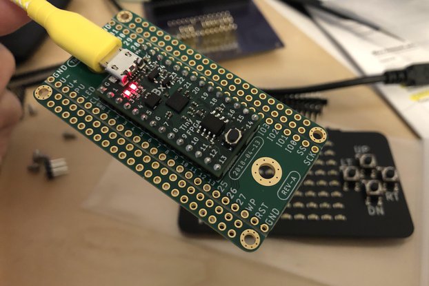
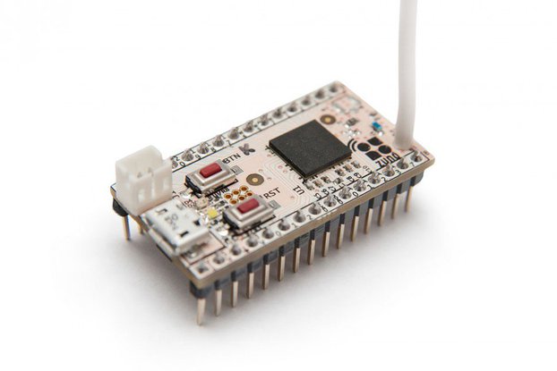
Prototype your own microcontroller mini-module. Generous prototype area. Onboard regulator. Solder bridges connect power to pins.
Designed by Electronics Design Services in United KingdomThis product is no longer available for sale.
The seller may be offering an improved version or it may be hanging out on the beach, enjoying the retired life.
You get a Matrix of 2 identical boards (NOTE: Bare PCB board only. No components supplied or fitted) Does your design end up looking like a birds nest? Issues with reliability and signal noise due to…
Read More…(NOTE: Bare PCB board only. No components supplied or fitted)
Does your design end up looking like a birds nest? Issues with reliability and signal noise due to trailing wires? Tired of rubbish ‘EVAL’ boards when all you want to do is get at the micro pins?
“Prototype your own application-specific microcontroller mini-module module – with prototyping area for housekeeping, SMT and through-hole components”
Suitable for ANY microcontroller with a matching LQFP footprint, including the STM32
For easier and cleaner prototyping. Without modification ALL pins of the device are connected directly to the header. Use as a standard breakout board for any LQFP device.
LQFP package size Will accept any wide or narrow body package: Pitch 0.5mm 48/64/80/100 pin device
Sent as a standard letter both domestically and internationally.
Features Prototyping area - Double-sided! Ideal for both SMT and through-hole components. - Extend your design with diodes, caps, regulators, XTALs and more - Plated vias allow signals to be passed from one side of the board to another - Easily route any of the 0.1" pin headers OR device pins directly to pads in the prototype area with the simple solder bridge links. - Pad pitch is 0.1"x0.05" or 100mil x 50mil AND a smaller 2.0x2.0mm area
Avoid the usual mess of power connections by using just solder links - Connect any micro pin directly to 0V or 3V3 loops provided. There's even a scope clip area - no more clipping onto the pin headers, it never stays!
Each pin header has multiple solder bridge options to allow for routing to the prototype area - or to ground. A single-track cut option also allows the pin header and the IC pin to be routed separately. There are too many use cases to list here - study the layout and you'll start to see the number of possibilities.
And so much more besides.. Each pin has a provision for two 0805 or 0603 devices. One is located on the top side, the other on the underside. (The topside will also accept a through-hole device) These can be used for decoupling caps, current limiting series resistor, pull-up, pull-down, series termination, parallel termination, clamping, TVS, high-pass filter, low-pass filter - and many others besides. Study the image of the layout and schematic to discover the possibilities.
Product: (5.00)
Documentation: (5.00)
Shipping: (5.00)
Communication: (4.00)
Carl | Aug. 19, 2021
$10.00
Free Shipping!
$8.00
Free Shipping!
$4.00
Free Shipping!
$6.00
Free Shipping!
By clicking Register, you confirm that you accept our Terms & Conditions
We recognize our top users by making them a Tindarian. Tindarians have access to secret & unreleased features.
We look for the most active & best members of the Tindie community, and invite them to join. There isn't a selection process or form to fill out. The only way to become a Tindarian is by being a nice & active member of the Tindie community!