Power, Interface, and Control Adapter shield for Reprap 3D printers 12V assembled version
Designed by Marty Rice in United States of AmericaThis seller is taking a break. Sign up below to get an email when they're back!
No shipping info available.
Set destination country to see options
Shipping to starts at
Free shipping is available to !
Ships from
This item does not ship to .
More Info
Sign up and we'll send a reminder when the seller returns!
This is the PICA Shield for Arduino Mega. It is a new rendition of the RAMPS design with improved power connectors and additional features. PICA is open-source hardware - follow the source code lin…
Read More…This is the PICA Shield for Arduino Mega. It is a new rendition of the RAMPS design with improved power connectors and additional features. PICA is open-source hardware - follow the source code link to the right to view all the project files on github.
The board is physically larger than RAMPS, which was unavoidable with the additional parts I wanted to add (and making the silkscreen more readable). The outer dimensions are 114x95mm (about 4.5" by 3.75") and there are four mounting holes located at the corners (located 108.6mm x 88.9mm center to center).
The screw terminals used on RAMPS are probably the biggest source of failure on the design (just google "RAMPS power connector melted"). They are barely rated to handle the kind of current we put through them, and it doesn't take much to result in a meltdown.
On PICA, I've replaced them with standard 0.25" quick connect solder tabs, and I think it's a huge improvement. The connection is much more secure and clean. Right-angle tabs are used for the power inputs, and a vertical version of the same connector is used for the higher current MOSFET switches.
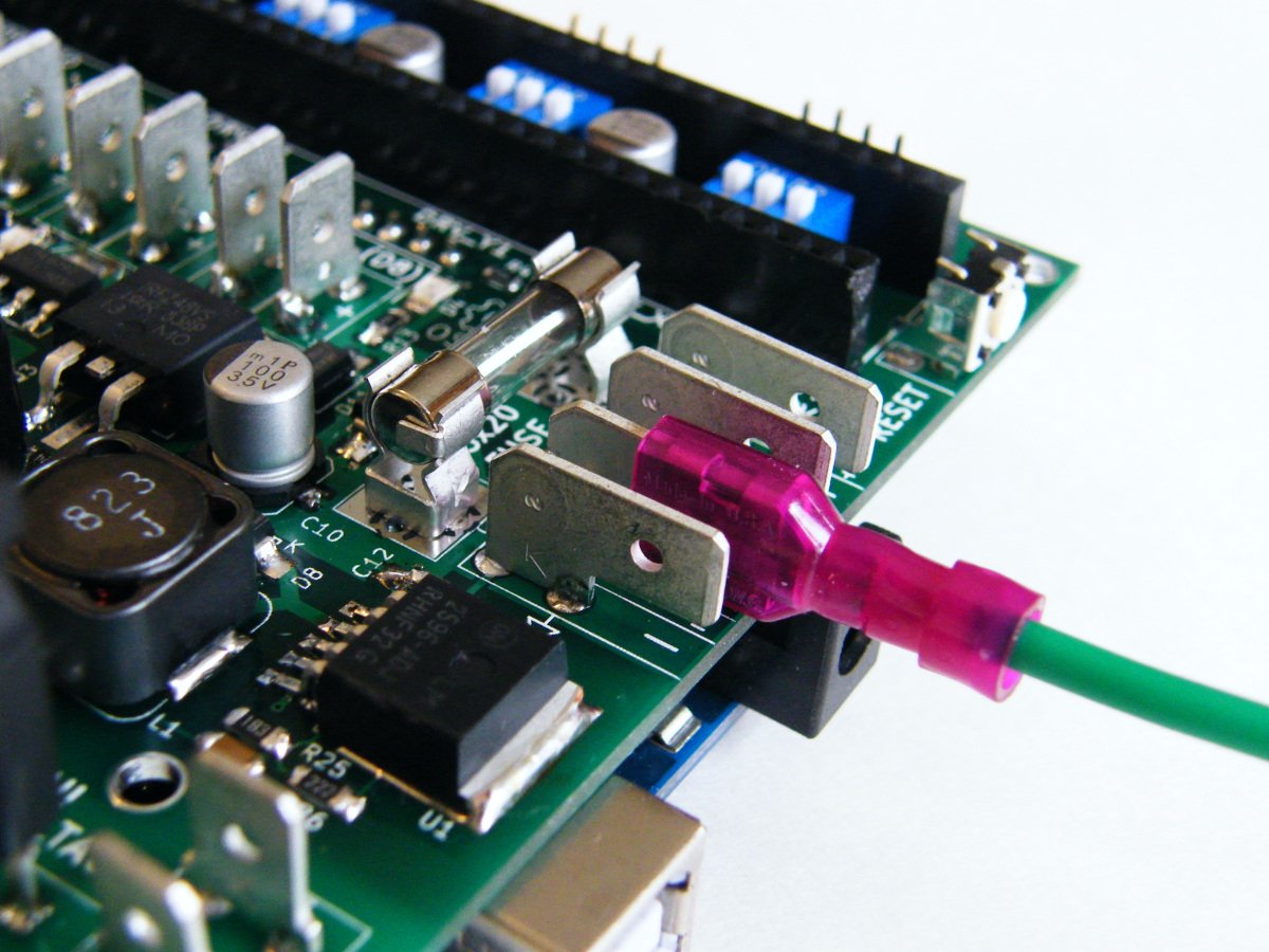
The power handling traces on RAMPS are simply too narrow, and over time may delaminate and fail. PICA is only a 2 layer board, but I did my best to stitch the various power nets and ground to planes wherever possible. This will make the board less prone to noise and will also conduct high currents more efficiently.
I've replaced the PTC fuses on the RAMPS design (those big yellow devices) with a single standard 5x20mm glass fuse. 15A should be the correct capacity. I've also combined the two power inputs, so they are actually just redundant and each feed the same circuits. On RAMPS, one of the 12V inputs was soley for the MOSFET driving the heat bed, and the other was for everything else.
The board is designed from the start to handle either 12V or 24V (or anything in between) on the power connectors. I've also added an on-board DC:DC converter circuit, based around the LM2596 buck converter, to provide an efficient 12V output from >12V input. You can build the board with or without this extra circuitry, so if you are using a 12V power supply (like I do) then it will be a little cheaper to build without it (just install the jumper P17 to connect the PSU input directly to the 12V power rail).
With the 12V converter, the PICA shield will let you intermingle 24V and 12V devices. This is really useful if, for example, you want to use 24V for the heatbed but still use 12V fans. There are a total of 5 MOSFET power outputs. These are all arranged as "open drain" devices which is exactly how RAMPS did it (with the addition of flyback diodes to protect the devices from spikes during turnoff, which were unfortunately absent on the RAMPS design). What "open drain" means is, the low side of the device being switched on and off is connected to the drain of the MOSFET, which is either high impedance (turned off so that no current can flow) or connected to ground (through the device's "source" pin) when the mosfet is turned on. The high side of the device being turned on or off is connected to a power supply rail (either 12V or 24V). More about the MOSFET switches in a moment.
There is also an independent linear regulator that provides a stable 5V source for logic and other devices on the shield. This is completely independent of the small LDO on the Arduino Mega. Overloading the Mega's regulator (and killing it) are a common problem if you are attaching other devices to the 5V supply (like servos). By keeping them separate, we can take the maximum power possible from the shield's 5V power supply without risking our Arduino. Also, the input to the on-board regulator (about 9V) also goes to the Arduino's VIN pin, so the Mega will still be powered by the shield regardless of whether you are running 12V or 24V.
I've expanded the number of switchable MOSFET loads from 3 to 5, and each one has a LED indicator to help you troubleshoot if you're not sure which ones are on.
One of these is meant as a "high current" load (up to 15A, which will usually be used for heatbeds).
The next two are "medium current" switches, capable of up to 5A individually. Like the heatbed switch, these two will operate directly from the power supply input voltage (up to 24V). The three high/medium power switches sport vertical QC tabs like the power inputs, so no fussy screw terminals for these either. The medium power outputs will most likely be used for hot end heater(s).
The next two FET switches are tied to the regulated 12V rail (which is either from the onboard Buck converter or straight from the PSU if you are using a 12V PSU) and can deliver 2A max each. In addition, these two have dual outputs so you can actually connect two devices to each, as long as you want them switched on and off simultaneously and the total load is within the 2A limit. These two switches are presented with 2-pin (2.54mm pitch) headers for easy connection to the most common style of fan wire harness.
All of the MOSFETs used are modern surface mount devices, chosen for their low on resistance, so things should stay relatively cool without any additional heatsinks.
Last but not least, if you have your sights set on controlling an AC powered device from your printer, PICA has an optional IXYS solid-state relay4 (SSR) capable of 5A@220VAC continuously. This should provide for a straight forward way to drive a AC heatbed, for example (during design testing I used it to switch a desk lamp on and off). You would just need to modify the pins definition in your firmware to designate the SSR enable line as your heatbed instead of the default (which connects to the first FET switch).
The two LCD interface connectors (previously attached to RAMPS via an intermediary circuitboard) are now directly on the shield. They should work directly with a variety of controllers such as the REPRAP SMART DISCOUNT controller and REPRAP FULL DISCOUNT CONTROLLER (you'll have to remap the pins, as described at the end of this post).
Along the lower edge of the PICA board, a variety of expansion pins are available. These include a generous number of auxiliary power output terminals (5V, 12V, and 24V if equipped). Most of them are standard 0.1" (2.54mm) spaced header pins, but I also included two different JST connector styles (2mm and 2.5mm) connected to 12V. These are common for example on DC fans.
There are also standard headers for I2C, SERVO/GPIO pins, and two serial port access. The layout of the serial ports should be compatible with the ubiquitous HC-06 bluetooth modules, and there are resistor dividers on the TX outputs to lower the signal level to be compatible with 3.3V devices.
Support for the PICA board can be integrated into Marlin easily by creating a custom board file and changing your board definition in configuration.h to "PICA". Below are the pin definitions that you will need:
#ifndef BOARD_NAME
  #define BOARD_NAME "PICA"
#endif


/* note that these are the "pins" that correspond to the analog inputs on the arduino mega.  these are not the same as the physical pin numbers
AD0 = 54;   AD1 = 55;   AD2 = 56;   AD3 = 57;
AD4 = 58;   AD5 = 59;   AD6 = 60;   AD7 = 61;
AD8 = 62;   AD9 = 63;   AD10 = 64;  AD11 = 65;
AD12 = 66;  AD13 = 67;  AD14 = 68;  AD15 = 69;
*/
/*************************************
 * PICA Arduino shield configuration mjrice
 ************************************* */

#if !defined(__AVR_ATmega1280__) && !defined(__AVR_ATmega2560__)
  #error "Oops!  Make sure you have 'Arduino Mega' selected from the 'Tools -> Boards' menu."
#endif

#define KNOWN_BOARD 1
#define LARGE_FLASH true

#define X_DIR_PIN         54
#define X_STEP_PIN        55
#define Y_DIR_PIN         56
#define Y_STEP_PIN        57
#define Z_DIR_PIN         58
#define Z_STEP_PIN        59
#define X_ENABLE_PIN      60
#define Y_ENABLE_PIN      61
#define Z_ENABLE_PIN      62

#define X_MIN_PIN         14
#define X_MAX_PIN         15

#define Y_MIN_PIN          16
#define Y_MAX_PIN          17

#define Z_MIN_PIN          23
#define Z_MAX_PIN          22

#define E0_STEP_PIN         67
#define E0_DIR_PIN          24
#define E0_ENABLE_PIN       26

#define SDPOWER            -1
#define LED_PIN            -1
#define PS_ON_PIN          -1
#define KILL_PIN           -1


#define SSR_PIN            6
#define HEATER_BED_PIN     8 // heat bed

#define HEATER_0_PIN       10 // extruder
#define HEATER_1_PIN       2 // second extruder
#define FAN_PIN            9
#define FAN_2_PIN          7

#define TEMP_0_PIN         9   // ANALOG NUMBERING
#define TEMP_1_PIN         10
#define TEMP_BED_PIN       10
#define TEMP_2_PIN         11
#define TEMP_3_PIN         12

// SPI for Max6675 or Max31855 Thermocouple
#if DISABLED(SDSUPPORT)
 #define MAX6675_SS       66 // Do not use pin 53 if there is even the remote possibility of using Display/SD card
#else
 #define MAX6675_SS       66 // Do not use pin 49 as this is tied to the switch inside the SD card socket to detect if there is an SD card present
#endif

// LCD interface pins
#define LCD_PINS_RS 33
#define LCD_PINS_ENABLE 30
#define LCD_PINS_D4 35
#define LCD_PINS_D5 32
#define LCD_PINS_D6 37
#define LCD_PINS_D7 36

#define BTN_EN1 47
#define BTN_EN2 48
#define BTN_ENC 31  //the click

#define BLEN_C 2
#define BLEN_B 1
#define BLEN_A 0

#define SD_DETECT_PIN 49
#define BEEPER_PIN   29
#define SDSS         53

#define LCD_SDSS 53

//encoder rotation values
#define encrot0 0
#define encrot1 2
#define encrot2 3
#define encrot3 1
No country selected, please select your country to see shipping options.
No rates are available for shipping to .
Enter your email address if you'd like to be notified when PICA Reprap Arduino Mega Shield can be shipped to you:
Thanks! We'll let you know when the seller adds shipping rates for your country.
| Shipping Rate | Tracked | Ships From | First Item | Additional Items |
|---|---|---|---|---|
|
:
|
Product: (5.00)
Documentation: (4.00)
Shipping: (3.50)
Communication: (5.00)
Alex | July 8, 2018
Jason | Nov. 25, 2017
No shipping info available.
Set destination country to see options
Shipping to starts at
Free shipping is available to !
Ships from
This item does not ship to .
More Info
Sign up and we'll send a reminder when the seller returns!
Northfield, OH, United States of America
Ships from United States of America.
54 Reviews | 1,081 Orders
$15.99
Free Shipping!
$12.00
Free Shipping!
$8.50
Free Shipping!
$31.00
Free Shipping!
$9.49
Free Shipping!
$11.00
Free Shipping!
$10.99
Free Shipping!
$9.99
Free Shipping!
By clicking Register, you confirm that you accept our Terms & Conditions
We recognize our top users by making them a Tindarian. Tindarians have access to secret & unreleased features.
We look for the most active & best members of the Tindie community, and invite them to join. There isn't a selection process or form to fill out. The only way to become a Tindarian is by being a nice & active member of the Tindie community!
