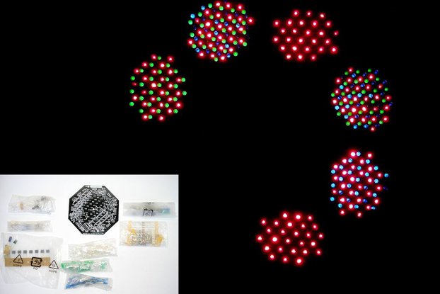
Display up to 16 high or low frequency logic signals on LEDs, or connect to your computer.
Designed by OmberTech in Australia
Buy with confidence.
Our Tindie Guarantee protects your purchase from fraud. Learn More
This is a kit for The Logic Visualiser, which provides a simple method of simultaneously viewing logic levels on any of sixteen inputs. Five operating modes are provided, allowing both slow and high-…
Read More…This is a kit for The Logic Visualiser, which provides a simple method of simultaneously viewing logic levels on any of sixteen inputs. Five operating modes are provided, allowing both slow and high-speed signals to be viewed. The Clock Division function allows repeating signals to be viewed in sequence even when operating at frequencies as high as 1MHz, while the data sampling mode allows data to be serially sampled from any input, then displayed over all the perimeter LEDs at a controllable rate.
With input buffers able to be configured for 5V TTL logic signals, or CMOS signals operating at 3V to 18V, the Logic Visualiser is a cheap and compact aid to designing, repairing, or demonstrating electronic circuits.
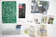
Provided with the kit are all components required for the construction of the Logic Visualiser PCB (but for the optional parallel port connector). Comprehensive online instructions detail the usage, and the circuit theory, of the Logic Visualiser, as well as a step-by-step description of construction accompanied by thirteen diagrams showing component placement. Also, a ribbon cable and IDC connector to form the basis of your test cable. Note that due to the variety of test connectors available, buyers must source the test probes separately to suit their application, suggestions are provided later in this description. A regulated 100mA 5VDC supply must be available to power the Logic Visualiser.
Full details at the Logic Visualiser webpage
| Specifications | |
|---|---|
| Inputs | 16 + Clock, Trigger, & Vinput |
| Input Impedance | 1Mohm |
| Max. Input Frequency | Greater than 1MHz |
| Input Logic Level | TTL/CMOS |
| Input Voltage Range | 5V TTL, 3-18V CMOS |
| Sampled Data Storage | 127 bits |
| Data Outputs | 8 |
| Output Logic Level | TTL |
| Supply Voltage | Regulated 5VDC |
| Supply Current | Less than 100mA |
The five operational modes of the Logic Visualiser are described in detail in the documentation. In summary...
Mode 1 (Internal Oscillator) shows the real-time logic state of the inputs, or can occasionally sample them so that conditions can be examined in circuits running too fast for the eye to follow. This mode can also be used to sequentially view repeating signals operating up to the lower KHz by careful adjustment of the operating frequency via the potentiometer, bringing the sampling frequency into sync with the clock frequency of the circuit being examined.
Mode 2 (Pulse) allows the input conditions to be sampled at the press of a button, and displayed for as long as required to analyse them fully.
Mode 3 (Clock Division) uses the clock signal from the circuit under examination to accurately sample the inputs at periods offset by one clock pulse, with delays up to numerous seconds (and able to be paused as required) allowed for viewing the input states. In this way, high-speed circuits with repeating signals can be viewed as if they were operating at a fraction of a Hertz.
Mode 4 (Data Sampling) stores 127 bits of data serially sampled from a selected input, and can then repeatedly display it across all the sixteen input state LEDs at a rate controlled by the potentiometer, and able to be paused as required.
Mode 5 (External Output) enables the input signals, converted to TTL levels, to be sampled by an external device such as a PC via the parallel port. A multiplexing method is used to allow all sixteen inputs to be accessed over an 8-bit data bus, allowing the Logic Visualiser to function as a sixteen channel logic analyser when used with the appropriate software.
The Fabulous Logic Analyser - 16 Channel (TFLA-16) software has been designed to support the Logic Visualiser.

The Alternative External Output mode (Mode 5a) allows existing PC parallel port logic analyser software and other devices to access eight of the inputs. Note though that in order to use this secondary mode (5a), modifications and some extra components are required (as described in the documentation). An additional kit including the parts for these modifications along with the parallel port connector is available.
Note: Some parallel ports with strong pull-ups on their data inputs have been found to be incompatible with the Logic Visualiser's data outputs. A buffer circuit, which can be built into the plastic shell of a DB25 parallel port connector, is described on the TFLA-16 webpage.

The standard kit contains one circuit board and all the components to build it and a 0.5m test probe cable (probes must be purchased separately). Sockets are provided for the three input buffer ICs, but not for the other chips. The colours of the button caps will vary. Some components are New Old Stock sourced from reputable suppliers. The full parts list can be found at the Logic Visualiser web page.
An option is provided for purchasing parts for an additional test cable, again without probes.
A DB25 socket suitable for connecting the Logic Visualiser to a computer via a parallel port can be purchased with the kit, and comes with parts to build the Alternative External Output modification (listed in the parts list). Purchase of a second test cable (nine more test probes required) is suggested if the Alternative External Output modification is performed. Two D25 sockets are available, the front of the metal one is slightly recessed behind the edge of the board and the mounting lugs must be bent forwards a bit before mounting on the board. The plastic ones protrude from the board, but must be mounted with separate nuts and bolts (supplied), with care taken not to damage the PCB tracks when securing the inner bolt. The plastic connectors may show signs of wear, the metal ones are new.
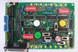
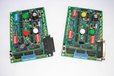
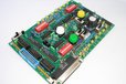
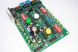
The images show Logic Visualiser boards built with both types of DB25 connector, the one with the plastic connector has also had the Alternative External Output modification performed.
One blue DIP switch and two red DIP switches will be provided in the kit, recommended for SW2 and SW1 respectively. Externally mounted rotary switches can also be used (though a DIP switch for SW1 is required for the Alternative External Output modification), see the documentation for details.
Suitable probes for the test cable can be purchased cheaply online. Search Ebay, Aliexpress, etc. for "test hook clip" for individual pin connectors of various styles, or "IC DIP Clip" for large clips designed to clip onto through-hole or surface-mount ICs (3D printable clip designs for this purpose are also available at "Thingiverse"). Other types of test probes are also available, such as plugs designed to fit into IC sockets. Twenty probes are required for all input connections.
PCI cards to add parallel ports to modern desktop PCs are also available very cheaply online, search "parallel port PCI".
This is a kit. Assembly required
Buy with confidence.
Our Tindie Guarantee protects your purchase from fraud. Learn More
$24.00

$29.50

$29.00
$11.00
$25.00
$7.80
$13.50
$5.00
$27.00
$12.00

$356.95
$498.95
/i/01031/products/2018-03-09T23%3A48%3A01.150Z-P1010072.JPG?1606306133)