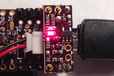
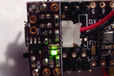
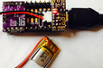
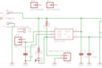
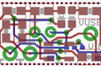
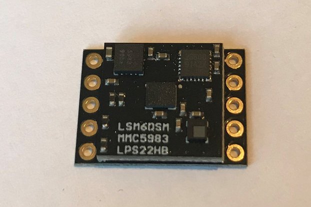
LiPo battery charger add-on for the Teensy 3.1
Designed by Pesky Products in United States of America
This product is no longer available for sale.
The seller may be offering an improved version or it may be hanging out on the beach, enjoying the retired life.
$49.95
$5.95
$35.95
$35.95
$49.95
$29.95
$19.95
$12.95

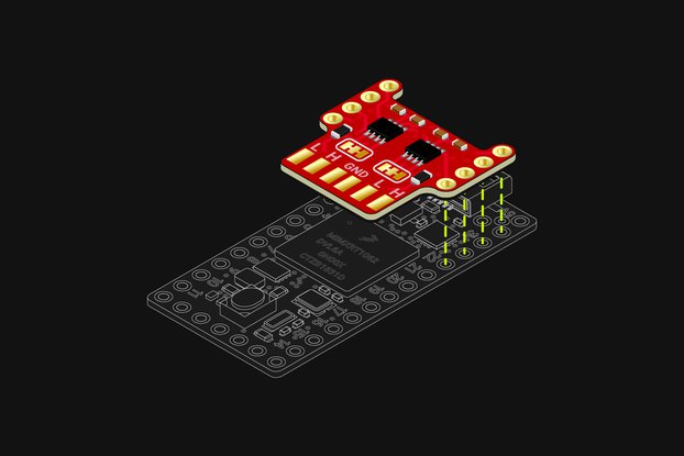
/i/44691/products/2014-08-20T03%3A43%3A23.822Z-LiPoChargerb.png?1606306133)