This board connects to your WiFi and sends a configurable text message, a short email or both.
Designed by PixelTwenty in United States of America
This product is no longer available for sale.
The seller may be offering an improved version or it may be hanging out on the beach, enjoying the retired life.
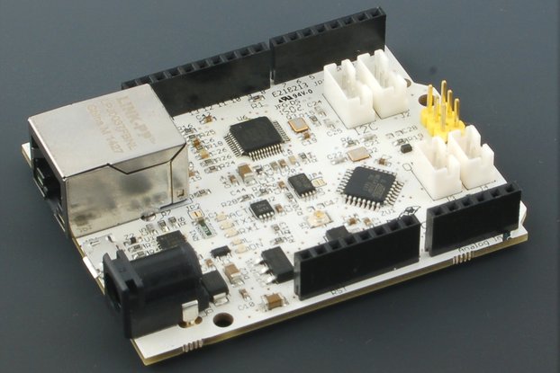
PixelTwenty ESP*Alert This board is an FCC certified ESP8266 programmed to send text and email alerts through PixelTwenty services when powered on or when a low is applied to the RST pin. A custom al…
Read More…This board is an FCC certified ESP8266 programmed to send text and email alerts through PixelTwenty services when powered on or when a low is applied to the RST pin. A custom alert message is sent depending on the state of one digital pin and the value of an analog input. Consumes only 90µA while waiting for a trigger – or 0µA with the addition of a 2N5060 transistor! Text messages (which cost a penny or so each no matter how you slice it) are routed through your own Twilio account created and funded by yourself. Use your own 6V power supply or buy one here.
PixelTwenty services utilize industry standard encryption and provide fault tolerance, failover, and five nines of availability. They also have the multiple validation mechanisms that email providers require in order to certify received messages as secure and trusted. Email alerts come from alerts@pixeltwenty.com.
The PixelTwenty ESP*Alert can be used right out of the box after a power supply and some sort of trigger are connected. Perform the software setup and you are up and running. The RST pin has an internal pullup resistor. You can use any sort of trigger your heart desires. Just bring the RST pin momentarily low. A momentary pushbutton switch or vibration sensor works, as well as an external open collector circuit.
It is OK if the trigger bounces as long as it does not bounce constantly or stay low for a long time – the alert is sent after the low is removed. See the 2N5060 addition below for trigger conditioning if needed.

Optional Alert Conditions
Alert conditions using #4 and the analog pin can determine which one of three messages is sent. The analog input is 0-1V. The resistor divider and formula shown below will scale a larger input voltage range to the required 0-1V. Pin #4 needs only to be pulled low to change its default state because it has an internal pullup resistor.

Zero Power and Trigger Conditioning
A couple of components can be added to achieve zero power consumption while waiting for a trigger. In this mode, the board is off until triggered with a positive signal to an external 2N5060 SCR instead of a negative pulse to the RST pin. The board sends the alert message, if any, then enters deep sleep. The low power consumption of deep sleep causes the SCR to turn off completely, and the board is ready for the next trigger. Any external circuitry connected to the board pins must not consume greater than 5mA or so as this will prevent the SCR from turning off.
This circuit will also take care of a trigger which bounces constantly or which does not change voltage once activated. The SCR effectively debounces the trigger input and will also activate the board only once if the trigger stays on.

Note that the analog input pin voltage must be scaled to 0 to 1.0V. Also, the maximum input voltage for GPIO is 3.3V – the #4 alert condition pin as well as the RST pin have internal pullups so you can filter out external positive input voltages (if any) using a diode and just worry about passing GND. When the board is off or sleeping, inputs and outputs will be in a floating state. Keep this in mind for your own external circuitry, if any.
WiFi
The board communicates using WiFi so a 2.5GHz 802.11 b/g/n or dual band AC WiFi router within range and connected to the internet is required.
Alert Conditions
The board waits to be turned on or, if already on, waits for a low pulse on the RST pin. The board then sends one of three messages depending on the setup configuration, the state of GPIO #4, and the value of the analog pin – or no message at all if no alert condition qualifies. Once triggered, the board evaluates the state of the #4 pin and if it is high and a message exists for #4 high, sends that message. Else if the #4 pin is low and a message exists for #4 low, the board sends that message. Else the board reads the value of analog pin and if the analog value meets the range qualification in the configuration and a message exists for analog, sends the analog message. Else the board sends no message, blinks the blue LED twice, and goes back to sleep.
Durations
Once triggered, if no alert condition qualifies the board will be on for about 3 seconds. It blinks the LED 2 times then goes back to sleep. If an alert condition qualifies and the board successfully connects to the internet through your WiFi router, the board will be awake for about 15 seconds as it sends the alert. If the board is having issues connecting to your WiFi router or to the internet through your WiFi router, it will try for 1 minute, blink the LED 5 times, then go back to sleep.
Blinks (2017 Devices)
Blinks (2018 Devices)
Reset Button
If the board is powered on (and even if in its waiting state), you can press and release the miniature reset button to simulate a trigger. This button is connected to the RST pin on the board and has the same affect as applying an external negative trigger pulse to that pin. If using the 2N5060 SCR option, the board is not normally powered on and the trigger needs to be directed instead to the gate of the SCR.
Receiving Alerts
An alert can be sent as an email, text message, or both. When an alert condition qualifies, an email is sent if the destination email address is configured and/or a text is sent if the Twilio credentials are configured. While messages are sent right away, if your mobile device is set up to check for emails on a 15 minute refresh schedule (for example) you may not get the email notification on that device until that refresh occurs, whether automatic or manual. In the remote chance that you do not receive an expected email, be sure to check your spam folder and mark the message as not spam. PixelTwenty services are completely configured as trusted and secure email sources, however spam designations can occur as with any email. Email alerts come from pixeltwenty.com.
Starting Setup Mode
If you have not yet set up your board, the board enters setup mode automatically when powered on. The blue LED blinks constantly in this mode. Setup mode can also be entered by powering up the board then immediately pressing and releasing the miniature button on the board labeled "GPIO0". The board has to be on and awake for this button to register. The button must be pressed before the board goes to sleep again.
Entering Setup
In setup mode the board creates its own WiFi network just for setup purposes. Using a WiFi enabled device (PC, Mac, phone, tablet) find the WiFi network named something along the lines of "PT" followed by 6 digits, like "PT123456" for example. Connect to that network using the password documented with your board. It can take anywhere from 5 to 45 seconds to connect. Once connected, open a browser and enter 192.168.4.1 in the address bar. The setup screen appears. If the setup screen does not appear or the browser displays an error, make sure your device is still connected to the board's WiFi and try again. The board will use the new settings when you save them. You can enter setup as needed to make future changes.
Exiting Setup
After saving the settings, power off the board or press the miniature button on the board labeled "Reset" to exit setup mode. If you press the reset button, the board will also conveniently go through a normal "triggered" phase. The board will attempt to connect to your WiFi and send an alert based on the settings you have given it.
Setup Screen

External Setup Button
If you wish to add an external button equivalent to the miniature "GPIO0" button on the board used for entering setup, a pushbutton switch can be connected to the pin labeled "#0" and to the board ground.
External LED
If you wish to add an external indicator equivalent to the blue LED on the board, a connection can be made to the pin labeled "#2" to drive an external LED, active low. Use an external buffer/driving circuit like a MOSFET if driving more than 10mA.
Send Indicator
The pins labeled "12" and "13" are outputs that are active low and active high, respectively, when an alert condition qualifies and the board is in the process of sending an alert. Use an external buffer/driving circuit like a MOSFET if driving more than 10mA.


/i/32458/products/2017-09-18T21%3A54%3A30.798Z-board_16_9_med.png?1606306133)