Connect up to 16 encoders on Arduino or ESP8266 board on the I2C bus!
Designed by DUPPA in Italy
This product is no longer available for sale.
The seller may be offering an improved version or it may be hanging out on the beach, enjoying the retired life.
Due to the new EU rules One Stop Shop (OSS) all the purchase from the EU are suspended on Tindie!
Join us on Telegram! https://t.me/joinchat/HklewhZ7mCPyivC1wdKs9g
Check the new version on Tindie! What is it? The I2C Encoder is a small board where you can use a rotary encoder with a I2C bus. The device also includes the possibility to add a bi-color LED and the…
Read More…The I2C Encoder is a small board where you can use a rotary encoder with a I2C bus. The device also includes the possibility to add a bi-color LED and the user can set luminosity through the I2C bus. It’s possible to connect up to 16 boards in cascade and read all of them with the same I2C bus.
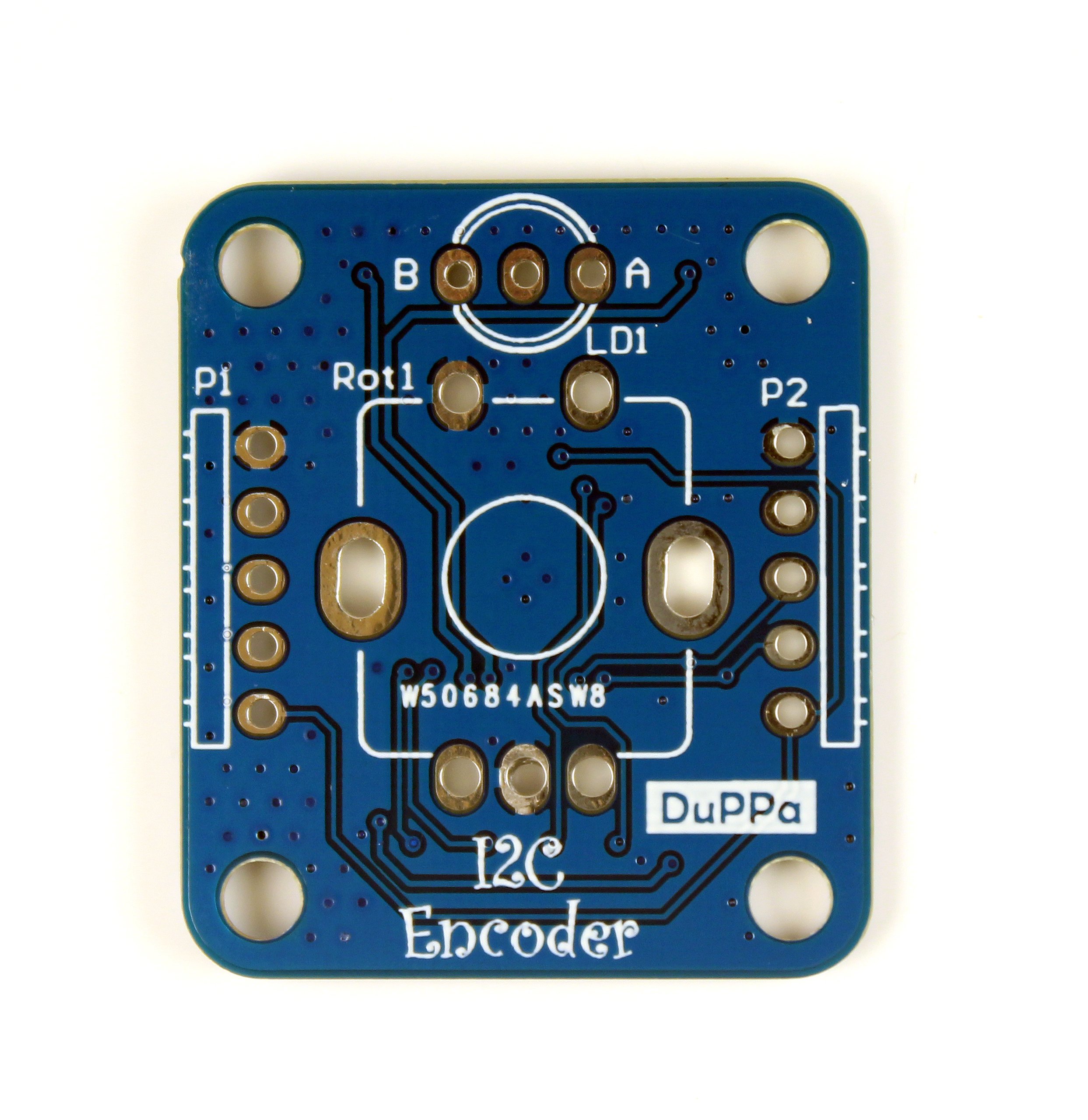
This product only includes the board without the encoder, connectors and LED. You can solder your favorite encoder, almost all the encoders have the same footprint, and you can directly solder the wires or put to a connector.
Here is an example:
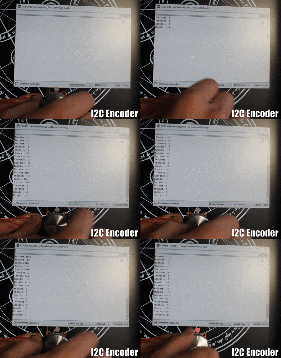
Usually a MCU with a few interrupt pins, like the Arduino MCU or the ESP8266, is difficult to add more than 1 encoder.
With this little board you can solve the above problem, no need to make your code full ofpolling routines. Plus you can connect a simple bi-color LED.
Tested with Arduino boards, Wemos and Raspberry Pi3
The I2C Encoder is a I2C slave, it’s possible to the set 16 different addresses. The last four LSB of the 7-bit address can be customized by soldering the jumpers A0 - A3 on the bottom of the board. When the jumper is open, it means a logic 0. if jumper is shorted it means a logic 1.
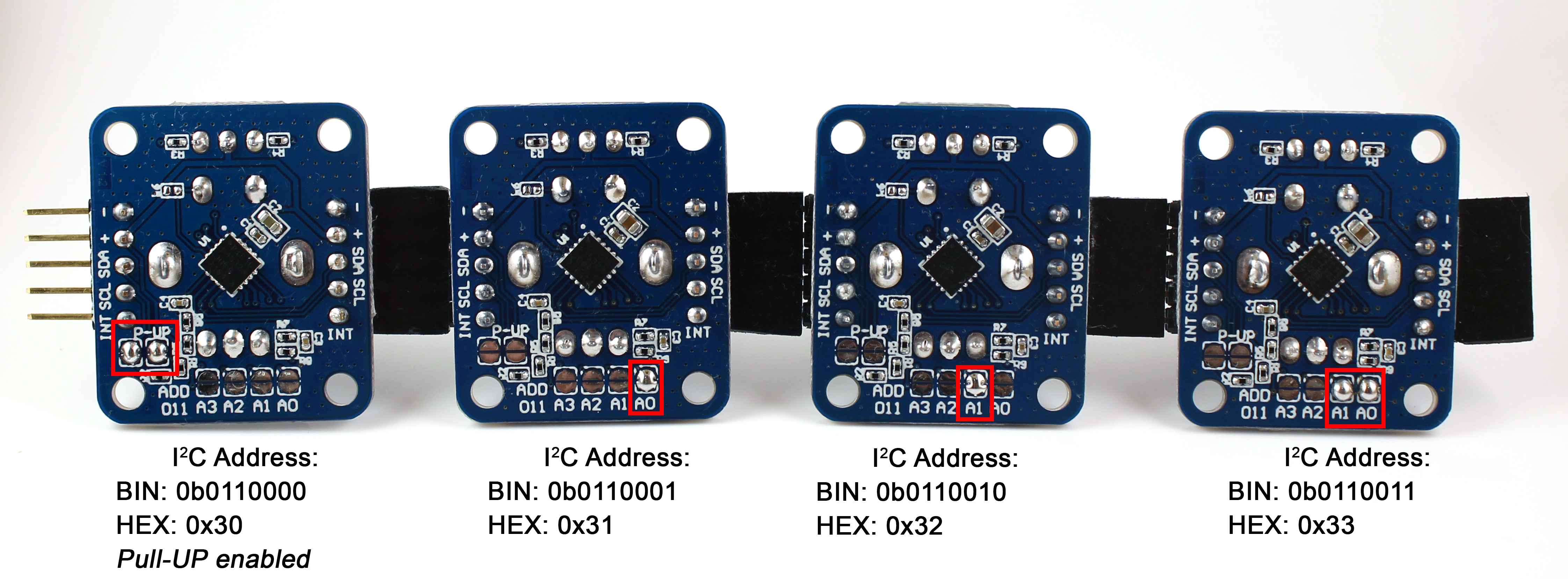
The I2C Encoder has the I2C pull-up resistors. They can be enabled by soldering the jumpers P-UP. This must be done in case of the master doesn’t have these resistors and must be enabled only one I2C Encoder in a chain.
In case the pull-up resistors is not needed, the jumper must be left open.
More documentation, source code and the Arduino library is available on GitHub
1 I2C Encoder board fully programmed (without encoder, connector and LED)
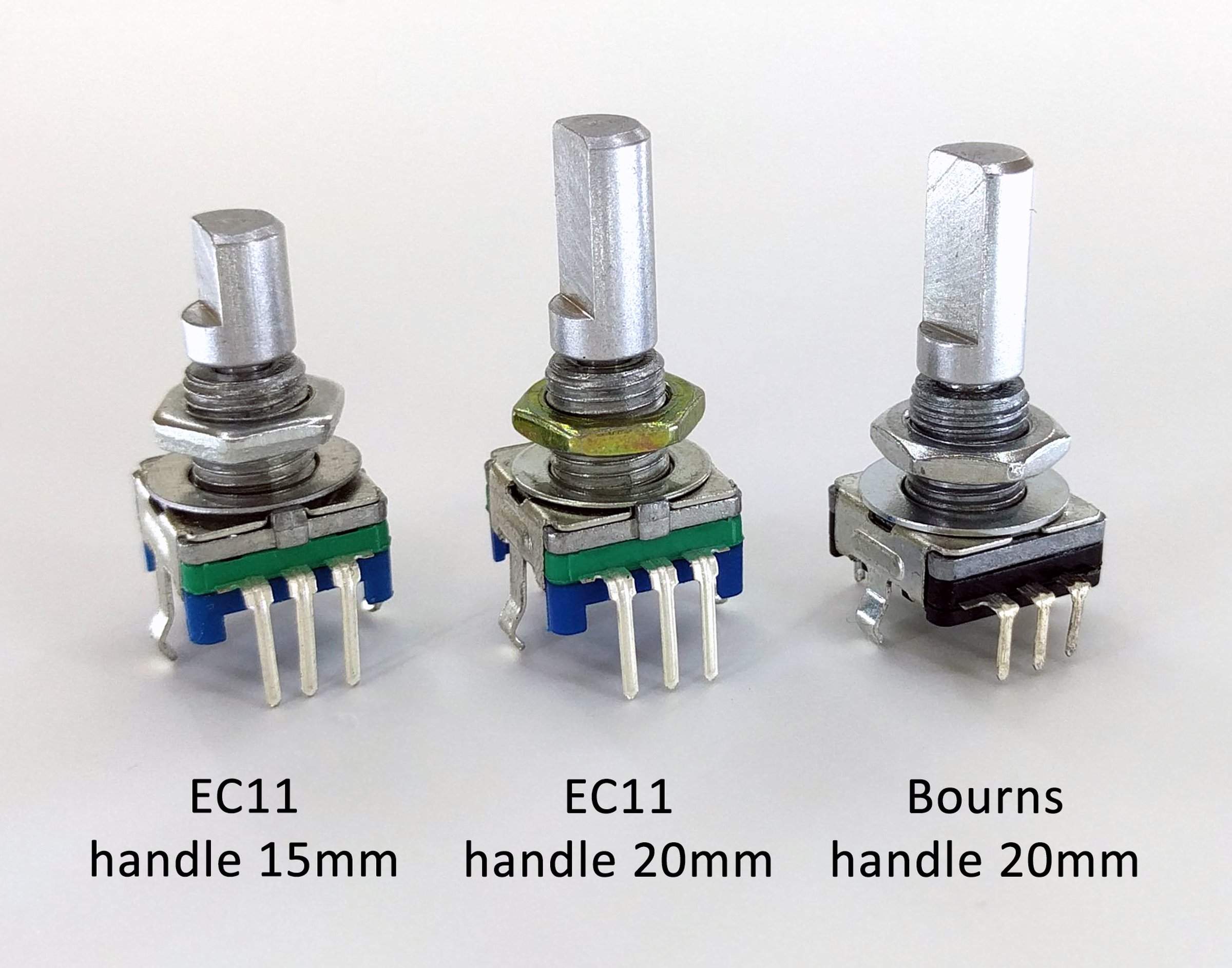
However, you can add "Accessory to be soldered" into your order according to your preference. There are 4 type of encoders. All have 20 pulses for rotation:
/*This example show how to read 4 I2C Encoder
All the 4 encoders will count between -20 and 20, the color of the LED will blink according to the direction of rotation.
The INT pin is readed in polling mode
Connections with Arduino UNO:
- -> GND
+ -> 5V
SDA -> A4
SCL -> A5
INT -> 12
*/

#include
#include "i2cEncoderLib.h"


#define ENCODER_N 4
const int IntPin = 12;
i2cEncoderLib encoder[ENCODER_N] = {i2cEncoderLib(0x30), i2cEncoderLib(0x31),
i2cEncoderLib(0x32),i2cEncoderLib(0x33)}; //Class initialization with the I2C addresses


int32_t counter[ENCODER_N] = {0, 0, 0, 0};
int32_t maxvalue[ENCODER_N] = {20, 20, 20, 20};
int32_t minvalue[ENCODER_N] = { -20, -20, -20, -20};
int32_t econfig[ENCODER_N] = {
(INTE_ENABLE | LEDE_ENABLE | WRAP_DISABLE | DIRE_RIGHT | IPUP_ENABLE | RMOD_X1 ),
(INTE_ENABLE | LEDE_ENABLE | WRAP_DISABLE | DIRE_RIGHT | IPUP_ENABLE | RMOD_X1 ),
(INTE_ENABLE | LEDE_ENABLE | WRAP_DISABLE | DIRE_RIGHT | IPUP_ENABLE | RMOD_X1 ),
(INTE_ENABLE | LEDE_ENABLE | WRAP_DISABLE | DIRE_RIGHT | IPUP_ENABLE | RMOD_X1 ),
};

uint8_t encoder_status;

volatile uint8_t i;
void setup(void)
{
  pinMode(IntPin, INPUT);
  pinMode(LED_BUILTIN, OUTPUT);
  Serial.begin(115200);

  Serial.print("Encoder Test!!\n");
  //Encoder Initialization
  for (i = 0; i < ENCODER_N; i++) {
    Serial.println(econfig[i], HEX);
    encoder[i].begin(econfig[i]);
    encoder[i].writeLEDA(0x00);
    encoder[i].writeLEDB(0x00);
    encoder[i].writeCounter(counter[i]);
    encoder[i].writeMax(maxvalue[i]);
    encoder[i].writeMin(minvalue[i]);
    encoder[i].updateStatus();
  }
}

void loop() {


  if (digitalRead(IntPin) == LOW) {
    digitalWrite(LED_BUILTIN, HIGH);

    for (i = 0; i < ENCODER_N; i++) { //Use a for loop for read all the 4 encoders
        if (digitalRead(IntPin) == HIGH)
            break;

      if (encoder[i].updateStatus()) {

        if (encoder[i].readStatus(E_INCREMENT)) {
          encoder[i].writeLEDA(0xff);
        }

        if (encoder[i].readStatus(E_DECREMENT)) {
          encoder[i].writeLEDB(0xff);
        }

        if (encoder[i].readStatus(E_PUSH)) {
          Serial.print("E");
          Serial.print(i);
          Serial.print(" Push\n");
        }

        if (encoder[i].readStatus(E_MAXVALUE)) {
          Serial.print("E");
          Serial.print(i);
          Serial.print(" Max\n");
        }

        if (encoder[i].readStatus(E_MINVALUE)) {
          Serial.print("E");
          Serial.print(i);
          Serial.print(" Min\n");
        }

        counter[i] = encoder[i].readCounterByte();
        encoder[i].writeLEDA(0x00);
        encoder[i].writeLEDB(0x00);
      }
    }

    for (i = 0; i < ENCODER_N; i++) { //print the final value
      Serial.print(counter[i], DEC);
      Serial.print("\t");
    }
    Serial.println();

    digitalWrite(LED_BUILTIN, LOW);
  }
}
| Quantity | Price |
|---|---|
| 1-4 | $6.90 |
| 5-9 | $5.85 |
| 10+ | $5.00 |
Product: (5.00)
Documentation: (4.80)
Shipping: (5.00)
Communication: (5.00)
Stefan | Aug. 19, 2018
Kim Bay | April 9, 2018
Giacomo | Jan. 14, 2018
Fabio | Dec. 30, 2017
Corneliu | Dec. 28, 2017
$32.00
Free Shipping!
$11.59
Free Shipping!
$6.70
Free Shipping!
$2.80
Free Shipping!
$16.95
Free Shipping!
$6.71
Free Shipping!
$12.90
Free Shipping!
$17.00
Free Shipping!
By clicking Register, you confirm that you accept our Terms & Conditions
We recognize our top users by making them a Tindarian. Tindarians have access to secret & unreleased features.
We look for the most active & best members of the Tindie community, and invite them to join. There isn't a selection process or form to fill out. The only way to become a Tindarian is by being a nice & active member of the Tindie community!
