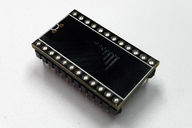
RF modulator replacement (RF delete) for the longboard Commodore 64 variants (ASSY# KU-14194HB, 250407, 250425 and 250466)
Designed by TheRetroChannel in Australia
This product is no longer available for sale.
The seller may be offering an improved version or it may be hanging out on the beach, enjoying the retired life.
Note: V2 has been replaced with the RFOFF - available here. The RF modulator in the C64 handles amplification and filtering for all video signals (including the ones on the C64 DIN connector). Unfort…
Read More…Note: V2 has been replaced with the RFOFF - available here.
The RF modulator in the C64 handles amplification and filtering for all video signals (including the ones on the C64 DIN connector). Unfortunately it does a very poor job and this is even more apparent with modern displays and upscalers, even CRTs with their inherent softening can reveal issues with the original RF modulator. One way to signifcantly improve the video output is to replace the RF modulator with a more modern and finely tuned solution, and why not add a few quality of life features while were at it.
This is an RF modulator replacement (RF delete) for the longboard Commodore 64 variants - these include ASSY KU-14194HB, 250407, 250425 and 250466.
Note ASSY 326298 is not compatible with either of these RF modulator replacements but there are some simple mods that can improve the video output of this revision.
Remove the original RF modulator, there are 4 tabs that need to be straightened and 4 grounding posts to be desoldered. You also need to desolder the 8 signal connections to the modulator - be very careful with these as they are easily damaged if not desoldered properly!
Insert the RF replacement into the mainboard (do not solder it in yet) and then the mainboard into the case. The rear ports should line up correctly in the case with no adjustment required. Once you have confirmed the alignment is correct, remove the mainbaord and proceed with soldering the ground posts and signal connections.
Set the selector switch to the desired "right channel" output. A 3.5mm to 2x RCA cable or splitter is recommended
Composite: Left channel is SID audio, right channel is composite video.
Dual Mono: Both left and right channels are SID audio.
External: Left channel is SID audio, right channel will be whatever is connected to the "input" pin nearby. The most common use for this would be dual SID setups or LumaCode. For example if used with Lumacode, LUM from the VIC-II-dizer would connect to "input", and GND to "ground".
Remember audio signals can be safely spilt, but not video signals. You can for example use the 3.5mm jack for composite video on the right channel, and split the left channel audio into left and right (dual mono).
The board can also safely drive both composite and S-Video outputs at the same time but not dual S-Video or dual composite (using both the RF replacement output and C64 DIN connector). In most cases you shouldn't need to use the C64 DIN connector, but all the standard video and audio signals will still be available there if required.
Commodore used a fixed value resistor for all longboard RF modulators which doesn't take into account variances in the video output of each and every VIC-II. I've added this option so the output can be tailored for your VIC-II and display combination.
Set the potentiometer to the mid position and power on the C64. Change the foreground colour to white: POKE53281,1 and the border colour to light grey: POKE53280,15
Adjust the potentiometer to obtain the ideal contrast. Too low and the white will appear light grey, too high will cause white to bloom and text will appear to shrink. This adjustment may also have an effect on jailbars if present in the borders, so it is recommended to play around until you find a sweet spot. Note this adjustment may have little to no effect depending on your display or upscaler - in which case it is recommended just to leave the trimpot at its mid position.
This option will only work with the Large VIC-II Kawari that outputs a DVI signal over a micro HDMI connector. A micro HDMI port replaces the S-Video connector and a flat flex cable (included) brings the HDMI from the Kawari to the rear of the 64 case. It is highly recommended to confirm the HDMI output from the Kawari is compatible with your display before ordering as it does not output a standard resolution. Please also keep in mind this is a DVI signal, as such it does not carry audio - that's what the 3.5mm jack is for!
Marvel at the beauty of your Commodore! Force your friends, relatives, and random people on the internet to do the same.
All boards are hand assembled and tested before shipping. As these are hand soldered, flux residue is included with every board at no additional charge ;-)
Product: (5.00)
Documentation: (5.00)
Shipping: (5.00)
Communication: (5.00)
Mark | March 18, 2024

$12.00
Free Shipping!

$35.00
Free Shipping!

$20.00
Free Shipping!

$35.00
Free Shipping!

$39.00
Free Shipping!

$35.00
Free Shipping!

$18.00
Free Shipping!

$18.00
Free Shipping!

$35.00
Free Shipping!

$55.90
Free Shipping!

$27.50
Free Shipping!

$15.50
Free Shipping!
By clicking Register, you confirm that you accept our Terms & Conditions
We recognize our top users by making them a Tindarian. Tindarians have access to secret & unreleased features.
We look for the most active & best members of the Tindie community, and invite them to join. There isn't a selection process or form to fill out. The only way to become a Tindarian is by being a nice & active member of the Tindie community!
