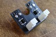
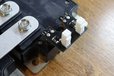
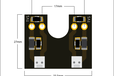
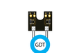
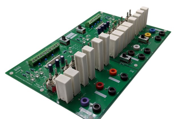
Preconfigured PCB for Tesla Coils, Induction Heaters, or other High Power Inverter Applications
Designed by WaskaLabs Designs in United States of AmericaThis product is no longer available for sale.
The seller may be offering an improved version or it may be hanging out on the beach, enjoying the retired life.
$217.00
Free Shipping!
$29.00
Free Shipping!
$13.95
Free Shipping!
$40.00
Free Shipping!
The gate drive board is a simple and quick way to set up an IGBT brick for high power applications. IGBT bricks have the ability to effectively switch loads of hundreds to over 1,000 Amps and handle …
Read More…The gate drive board is a simple and quick way to set up an IGBT brick for high power applications. IGBT bricks have the ability to effectively switch loads of hundreds to over 1,000 Amps and handle voltages as high as 1,200V. These systems can be very useful for an array of high power applications such as:
The board is designed for use with half-bridge IGBTs and is compatible with many bricks including the SKM and CM series. Make sure to check the dimensions of your brick to assure they are compatible. The brick gate driver has 4 x 2.8mm female quick connectors that plug the PCB directly into the brick. The system is intended to be run from a separate gate drive transformer (GDT) that can be hand-wound or purchased in my store. The components on the board include a series gate resistor for reducing inrush current (useful for eliminating voltage spikes and to increase the lifetime of the bricks), Schottky diodes across the resistors in reverse for fast gate discharge time and low switch-off losses, and a TVS diode for gate overvoltage protection. Note that the TVS should always be rated at least a few volts higher than you will be driving the gates! (e.g. SMAJ18 18V if using 12-16V drive, SMAJ26 26V if using 24V drive, etc). The board also has an opening in the center for easy access to the IGBT mounting holes on center mounted modules such as the SKM100.
The board comes set up with the SMD components and quick connects pre-soldered. The male polar connectors are not soldered to allow for optional phasing of multiple IGBT modules into a full bridge configuration (see application notes below and diagram in photos). By default it is set up for a 24V drive voltage from the GDT. The components used are:
Application Notes:
Not all components are required. Tuning the gate drive circuit and testing different components and values may be necessary for perfect operation, however I have found the default components to be a happy medium that should work on many designs. Some designs may work better without the addition of the TVS diodes. All of this varies with things like frequency, drive current, etc - just note that tuning of the circuit may be needed for your application.
If using two bricks in a full bridge topology, be sure to invert the phasing on one of the bricks. I do this by flipping the polar connectors upside-down on one of the PCBs and phasing all the gate drive transformer connectors in the same direction so that they plug directly in and there is no possibility of driving the bricks in the same direction. (e.g. you DONT want to phase the GDT outputs opposite. If you get them mixed up, you can blow the bricks). Check the photos for the "Full Bridge" topology and note the MOLEX connectors on the PCB are flipped.
If you have any questions please let me know!
Quantity | Price |
---|---|
1 | $10.00 |
2-3 | $9.00 |
4+ | $8.00 |
$10.00
Free Shipping!
$134.99
Free Shipping!
$195.00
Free Shipping!
$140.00
Free Shipping!
By clicking Register, you confirm that you accept our Terms & Conditions
We recognize our top users by making them a Tindarian. Tindarians have access to secret & unreleased features.
We look for the most active & best members of the Tindie community, and invite them to join. There isn't a selection process or form to fill out. The only way to become a Tindarian is by being a nice & active member of the Tindie community!