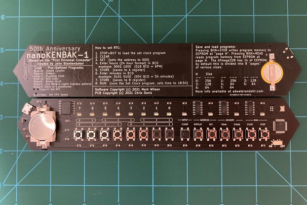
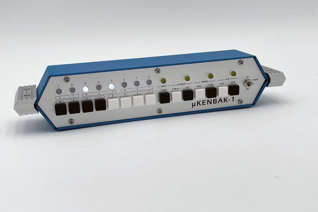
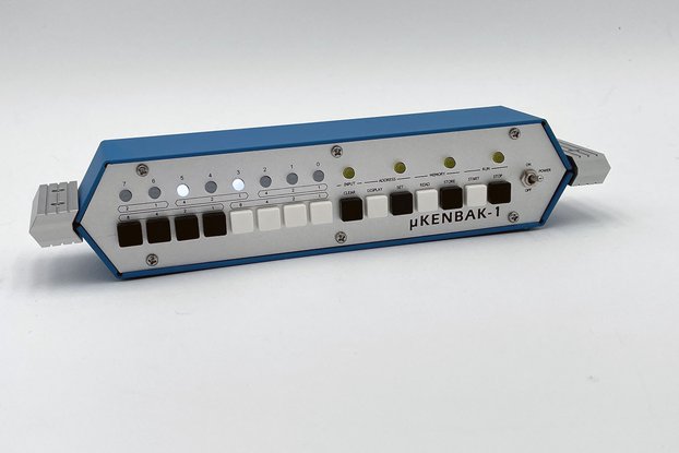
Fantastic kit, communicative seller, alright documentation
For Altair-Duino Pro
I've made a much older version of this kit years ago, with a bamboo box. I love it, and decided recently to pick up a new and improved version. It arrived quickly and I got to work putting it together, but unfortunately I realized that I didn't put the header pins on the right way around (you're supposed to have the long ends sticking out towards where the arduino will be mounted), and the arduino didn't make good enough contact with the PCB, making it unusable. While that is absolutely my fault, I will say that I think the manual should include some warnings to double check critical components such as that before committing to soldering them, not just a picture of the arduino with the pins on it. Ultimately however it would probably be best to do this kit in breaks, as at least for me I tend to zone out and not pay as much attention after spending long periods soldering.
I reached out to Chris over email and asked him if I could send my kit in for repair, as I did not know at the time that you could simply cut the header pin plastic separators off and then desolder each pin much more easily. He quickly responded and agreed to have it sent over. Unfortunately UPS lost my board during shipping, and after I got the insurance check I ordered another PCB and set of components to make a new board. I've learned a lot from that experience.
Here's a few suggestions:
Make sure you pay close attention to the color and type of your toggle switches, as well as which direction you solder them! There's no going back once you commit. Top row of switches should on/off toggles, as well as the power switch on the bottom row. The bottom row of switches however is a series of momentary toggles.
There's no mention of which side the 47uF capacitor should face, but you should pay close attention to the picture and make sure the side with the line is oriented properly.
On my first PCB I found that the LEDs didn't sit flush. With the new PCB I found that if I gently shook the LEDs once they had already dropped into the front panel, they'd seat better. Then I just used my tweezers to gently guide the remaining ones down so that all of them fit flush in the panel. I found that soldering one side at a time kept the components from getting hot, especially the header pins, sockets, LEDs, and capacitors, so it might be a good idea to do them just like the toggle switches later on in the manual. It also makes it easier to keep the LEDs in alignment.
If you ever need to remove header pins you simply cut the plastic off with your cutters, then heat the solder up and use tweezers to gently push out the pin. Afterwards you can use some flux on the pin and solder wick to suck up the solder. You may want to go back and hit it with your solder sucker as well to remove any remaining solder from the pin so that a new header will fit. Don't tug if the pin doesn't want to come out, and do not let your iron sit too long on the joint. You can risk damaging the pad. If the pin isn't coming free try using more flux and adding more solder.
For removing the switches you can add enough solder to bridge the three terminals, then heat it up and gently rock the switch out. Afterwards do the same thing as you would after removing header pins to clean up the holes. You will destroy the switch, but it will be removed.


